Laminated Shingle With Wider Nailing Zone

a technology of laminated shingles and nailing zones, applied in the field of laminated shingles, can solve the problems of roofers failing to apply nails, affecting the adhesive quality and deformation resistance, slowing down the speed of shingle application, etc., and achieves the effect of high softening poin

Active Publication Date: 2006-11-30
CERTAINTEED CORP
View PDF10 Cites 76 Cited by
  • Summary
  • Abstract
  • Description
  • Claims
  • Application Information

AI Technical Summary

Benefits of technology

[0015] It is yet another object of this invention to provide a laminated shingle having a wide nailing zone, without having a wide double-layer nailing zone, by using a high temperature softening point adhesive or an adhesive that does not soften at high temperatures or an adhesive having a high shear modulus, to secure the layers of the laminated shingle together, such that it is no longer necessary to nail the shingle through both layers of the laminate in order to retain the posterior layer on a roof.

Problems solved by technology

Professional roofers find this width too narrow, as it interferes with efficient fastening of shingles to a roof, slowing down the speed of shingle application.
Where laminated shingles have a common bond area that is too narrow, such as 1 inch or less, there can be a tendency for roofers to fail to apply the nail or staple fasteners into the common bond area, but to apply their fasteners above the common bond area, such that the fasteners pass through only the anterior shingle layer, and do not intercept the upper portion of the posterior shingle layer.
With such softening of the bitumen-based adhesive, there leaves the possibility, especially for roofs of steeper pitch or slope, that the posterior shingle layer of any given shingle, if the fasteners have not penetrated such posterior layer when the shingle was applied to the roof, the posterior shingle layer, under its own weight, may overcome the adhesive quality and deformation resistance of the softening bitumen, and slide out beneath the anterior shingle layer, at least compromising the quality of the roof.

Method used


Image

  • Laminated Shingle With Wider Nailing Zone
  • Laminated Shingle With Wider Nailing Zone
  • Laminated Shingle With Wider Nailing Zone

Examples


Embodiment Construction

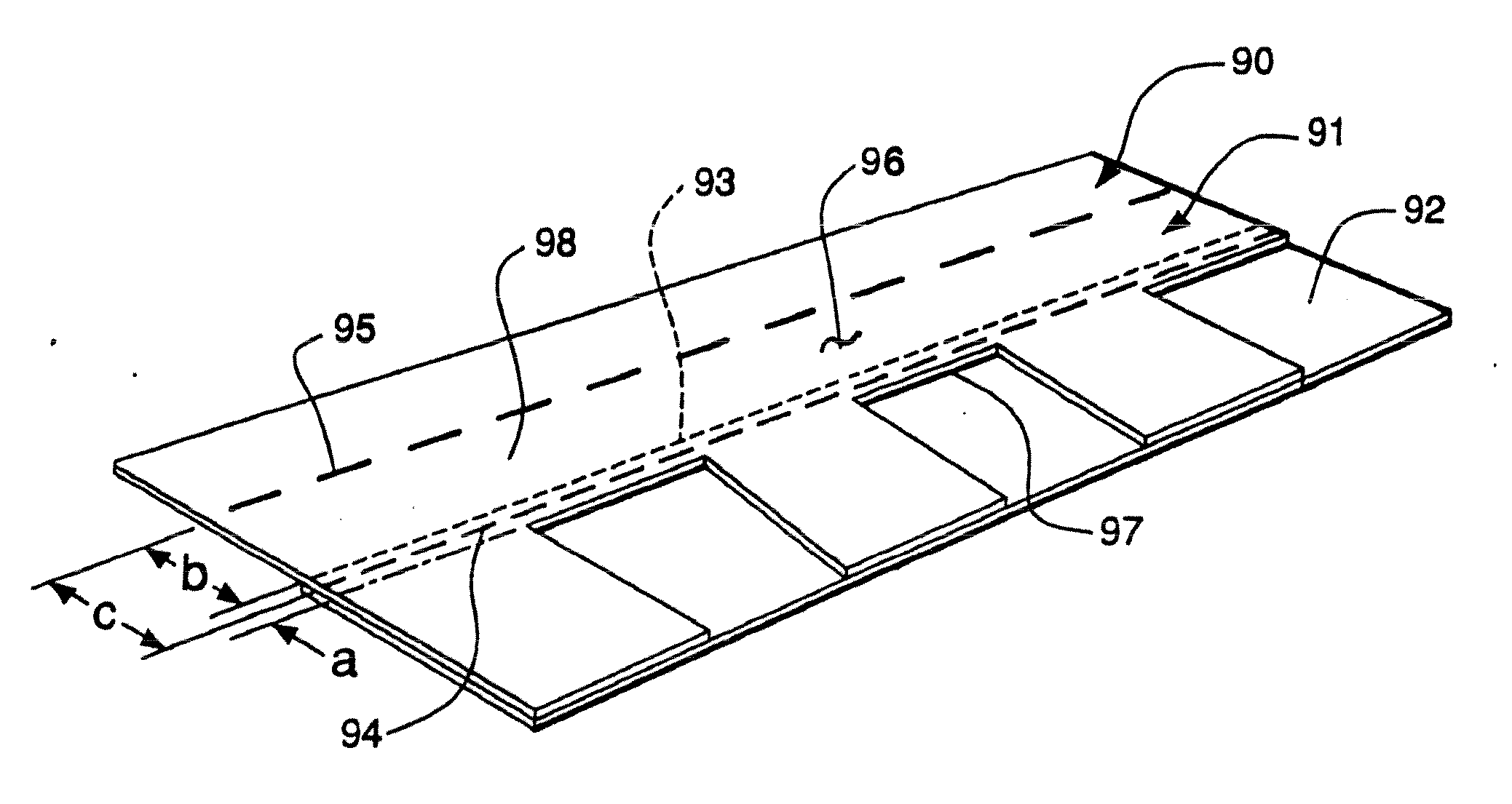
[0026] Referring now to the drawings in detail, reference is first made to FIG. 1, wherein a prior art shingle is generally designated by the numeral 10, as having an anterior shingle layer 11 and a posterior shingle layer 12. The anterior shingle layer 11 has a plurality of tabs 13, separated by substantial cut-outs 14, spaced apart by the tabs 13, and formed as sizable slotted openings between the tabs 13. The shingle of FIG. 1 is often referred to as a multiple-ply dragon-tooth design.

[0027] The anterior shingle layer 11 has a front surface 15 and a rear surface 16. The posterior shingle layer 12 has a front surface 17 and a rear surface 18. The posterior shingle layer 12 has an upper edge 20. The cut-outs 14 in the anterior shingle layer 11 have an upper edge 21. Widthwise, the longitudinal area between the upper edge 21 of the cut-outs 14 and the upper edge 20 of the posterior shingle layer defines the common bond area 22, which runs from the right-most edge 23 of the shingle ...


PUM

PropertyMeasurementUnit
softening pointaaaaaaaaaa
widthaaaaaaaaaa

Abstract

A multiple-layer laminated shingle and a method of making the shingle are provided, in which at least one adhesive of high temperature resistance is applied for securing the shingle layers together, to reduce reliance on a roofer having to fasten (via nails, staples or the like) through a narrow headlap zone of a posterior shingle layer in order to secure the posterior shingle layer to a roof, such that a vertically wide portion of the headlap area of the anterior shingle layer is presented to the roofer as a nailing zone.

Description

CROSS-REFERENCE TO RELATED APPLICATION [0001] This application is a divisional of U.S. Ser. No. 10 / 289,441 filed Nov. 6, 2002.BACKGROUND OF THE INVENTION [0002] Laminated shingles are known in the art to be made from asphaltic roofing material overlaid upon one another, and secured together by means of an adhesive to provide a shingle having a thicker section. The anterior layer of the shingle has alternating tabs and cut out portions in the form of slots of various dimension in the lower end of the shingle, and an upper end of the shingle that is not divided into tabs. The posterior shingle layer, often called a backing sheet is applied, generally to the rear surface of the lower end of the anterior shingle layer, covering the rear surfaces of the tabs, such that the two shingle layers are not coextensive in area. [0003] In applying the shingles to a roof, by means of fasteners such as nails, staples or the like in accordance with the teachings of the prior art, there is a longitud...

Claims


Application Information

Patent Timeline
Patent Type & Authority Applications(United States)
IPC IPC(8): E04D1/00B32B38/10E04D1/26
CPCB32B37/1284Y10T428/24752E04D1/26B32B38/10
Inventor KALKANOGLU, HUSNU M.STAHL, KERMIT E.DONALDSON, JOHN K.
Owner CERTAINTEED CORP
Why Eureka
Try Eureka