
Sampling tool

a technology of sampling tool and sample, which is applied in the field of sampling tool, can solve the problems of difficulty in extracting the sample from the conical recess, complicating manual removal without a degree of dexterity, and further risk of contamination of the sample by the operator's fingers

Inactive Publication Date: 2006-11-30
AGRESEARCH LTD
View PDF19 Cites 7 Cited by
  • Summary
  • Abstract
  • Description
  • Claims
  • Application Information

AI Technical Summary

Benefits of technology

"The present invention provides a sampling tool with a fluid conduit for applying elevated pressure to a sample-retaining portion through a tool head. The tool head may have a conical, spade / chisel, screw or auger-shaped, or a pair of opposed cutting surfaces, and may be used in a variety of test materials. The method involves inserting the tool head into the material, withdrawing it with the sample retained in the sample-retaining portion, and applying elevated pressure to the sample-retaining portion to expel the sample. A reduced pressure may also be applied to remove any air or other undesirable materials from the sample before the elevated pressure is applied. The technical effect of the invention is the ability to easily and consistently expel samples from the sample-retaining portion without the need for further intervention from the user."

Problems solved by technology

However, with existing samplers, there remains the difficulty of extracting the sample from the conical recess.
Firstly the sample volume is relatively small and this complicates manual removal without a degree of dexterity.
Furthermore, unless some further form of instrument such as tweezers, forceps and so forth is used to aid extraction, there is further risk of contamination of the sample by the operator's fingers.
Many samples such as meat are relatively fibrous and / or sticky further hindering the removal of the sample from the conical cutter.
However, there is no disclosure of an aid to dislodge the retrieved sample from the sampling device.
However, there is no disclosure of an aid to dislodge the retrieved sample from the sampling device, nor of the inclusion of any fluid / liquid lines to the tool head.
However, the mechanical configuration of the device is complex and does not lend itself to rapid sampling.
However, there is no disclosure of a means of enhancing the extraction / ejection of the sample.

Method used


Image

  • Sampling tool
  • Sampling tool
  • Sampling tool

Examples


Embodiment Construction

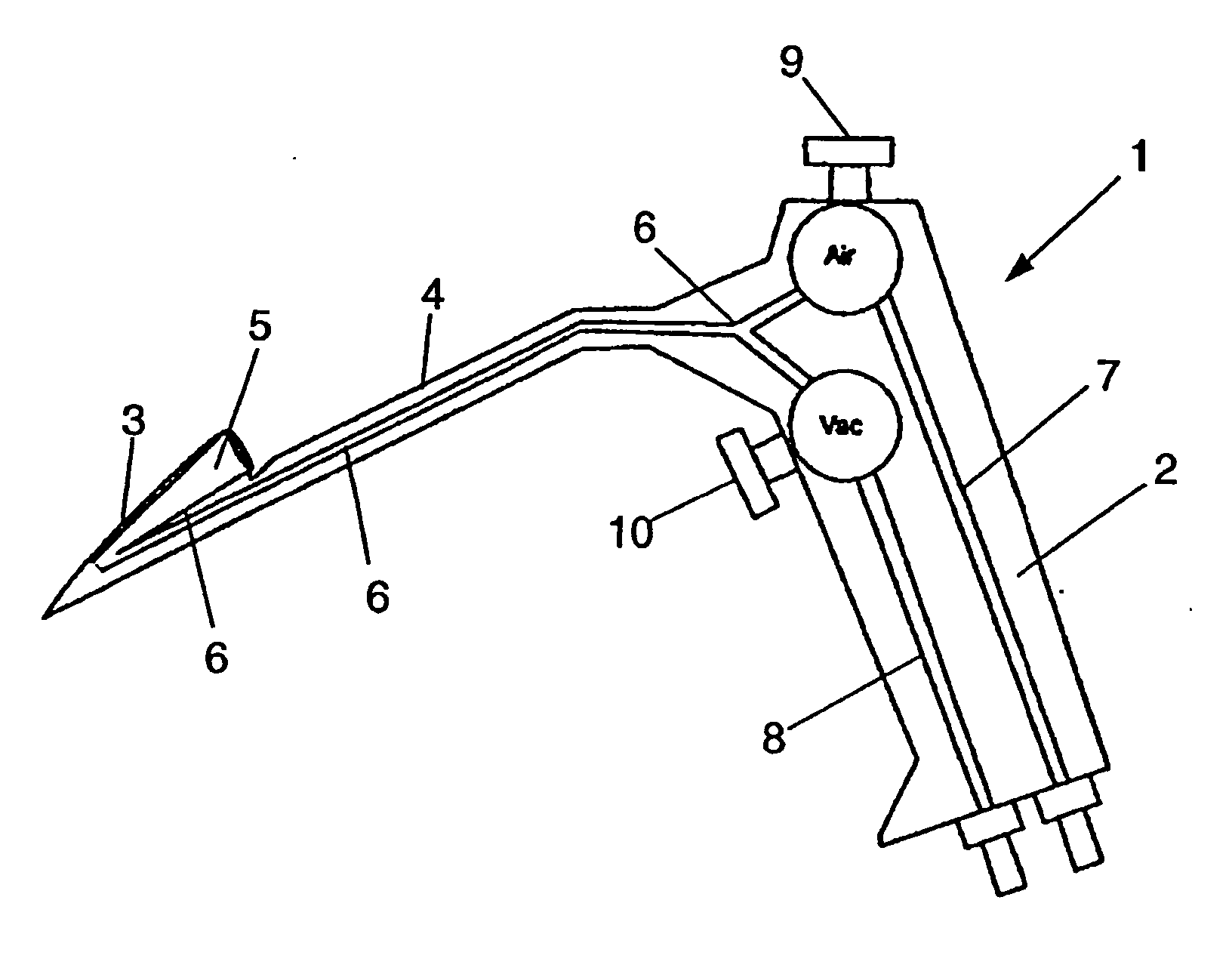
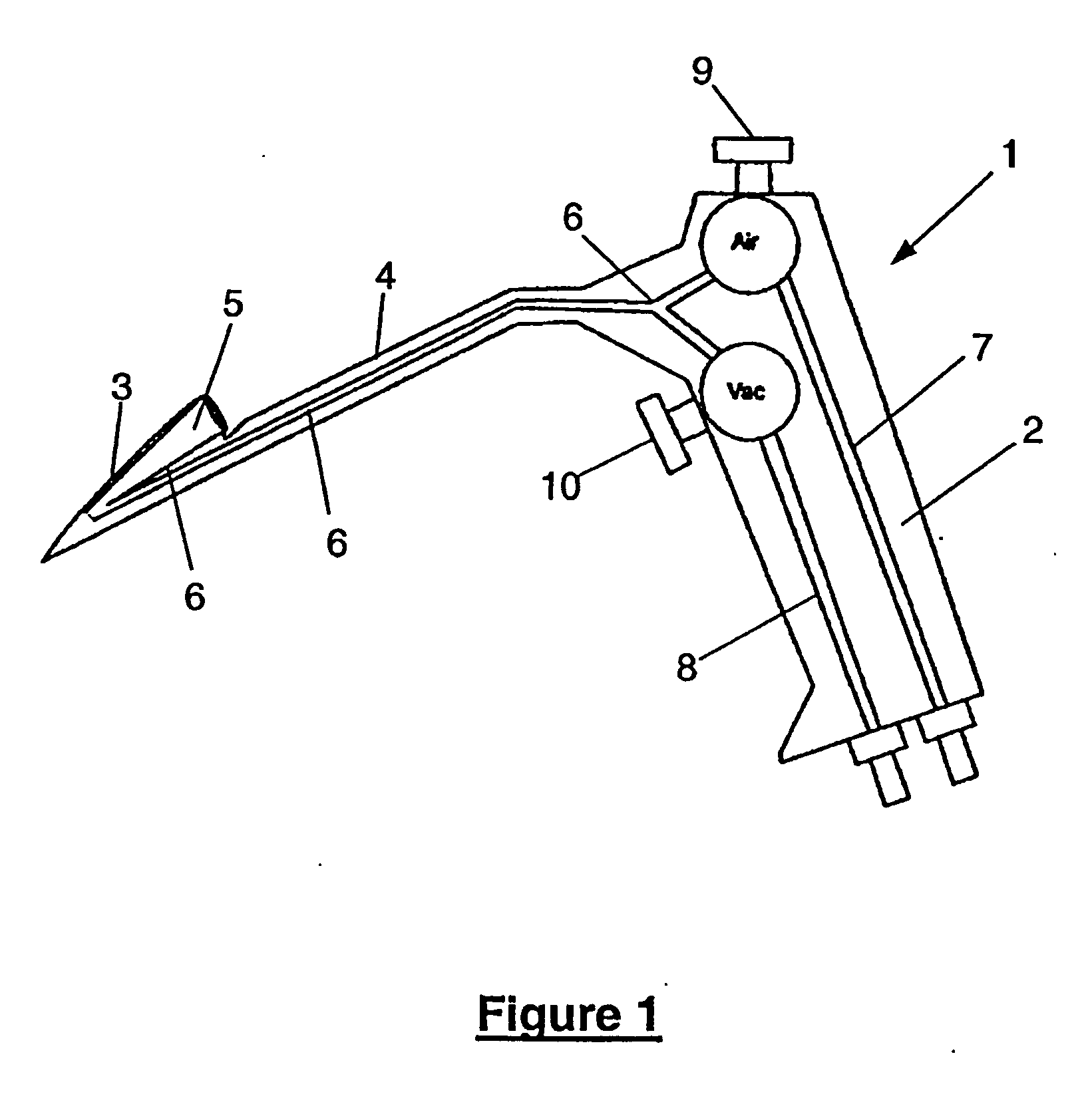
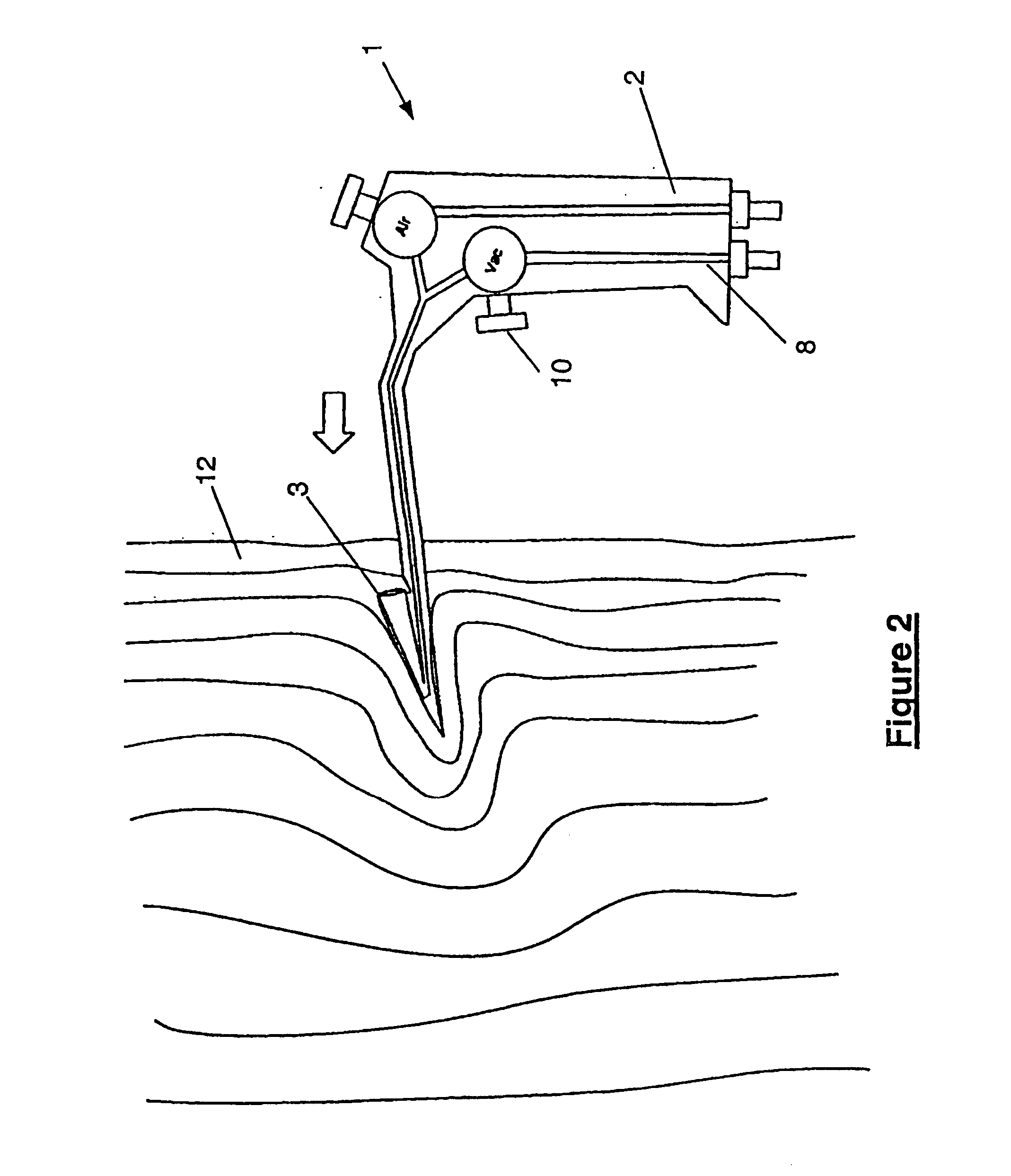
[0054]FIGS. 1-4 show a preferred embodiment of the present invention in the form of a sampling tool (1) comprised of a handle (2), attached to a tool head (3) via an elongated shaft (4).

[0055] In the embodiment shown, the tool head is a substantially hollow conical element open at the base to provide an inner recess of complementary conical shape to the exterior shape. The inner recess provides a sample-retaining portion (5) and is orientated to present the circular open base of hollow cone towards the elongated shaft (4) and away from the direction of insertion of the tool head (3) into a sample volume.

[0056] The sampling tool (1) further includes a fluid conduit (6) which extends from the sample-retaining portion (5) through the tool head (3), along the elongated shaft (4) to the handle (2). In the handle (2) the fluid conduit branches into two further conduits (7, 8) which are respectively connectable to separate external pressure source. An elevated pressure source in the form...


PUM

PropertyMeasurementUnit
electroconductiveaaaaaaaaaa
coloraaaaaaaaaa
luminescenceaaaaaaaaaa

Abstract

A sampling tool (1) including a tool head (3) with a sample retaining portion (5) characterised in that said sampling tool (1) further includes a fluid conduit (6) extending from the sample-retaining portion (5) through the tool head (3), and a method of obtaining a sample (11) using said sampling tool (1), said method including the steps of inserting said tool head (3) into a test material (12); extraction of said tool head (3) from the test material (12) together with a sample (11) of said material (12) retained in said sample retaining portion (5); characterised in that; an elevated pressure is applied via said fluid conduit (6) to said sample-retaining portion (5) to expel said sample (11).

Description

TECHNICAL FIELD [0001] The present invention relates to a sampling tool and a method of using same for use in removing smaller sample portions from larger objects for substances for testing. In particular, the present invention is particularly suited for use in extracting organic samples such as meat and the like. BACKGROUND ART [0002] It is necessary to remove small sample portions of meat, cheese, and other organic matter for a variety of tests before the produce reaches domestic consumption. If the produce is destined for export or other high cost activities, it is further desirable to identify and reject any contaminated or low quality produce before transportation occurs. [0003] To enable accurate testing procedures to be performed without bias from the effects of surface contamination and atmospheric effects, a sample must be retrieved from the central body of the material. [0004] Conventional techniques for achieving this end utilise a shaped hollow conical cutter element loc...

Claims


Application Information

Patent Timeline
Patent Type & Authority Applications(United States)
IPC IPC(8): G01N1/04G01N1/08
CPCG01N1/08
Inventor GRAHAM, DONALD MICHAEL
Owner AGRESEARCH LTD
Learn More