
Filter

a filter cloth and filter technology, applied in the field of filters, can solve the problems of affecting the filtering capacity of the filter only to a small extent, and neither of the filter cloths is able to filter efficiently

Inactive Publication Date: 2006-11-30
AISAN IND CO LTD
View PDF18 Cites 21 Cited by
  • Summary
  • Abstract
  • Description
  • Claims
  • Application Information

AI Technical Summary

Benefits of technology

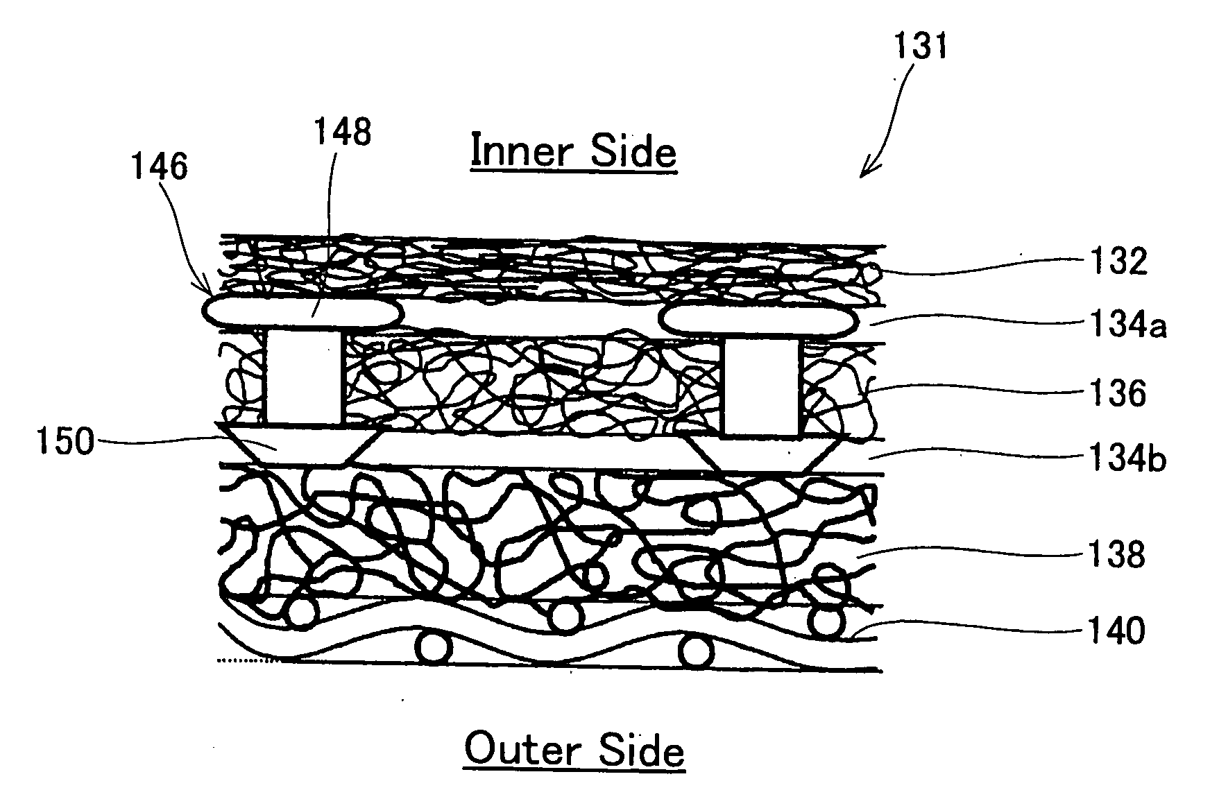
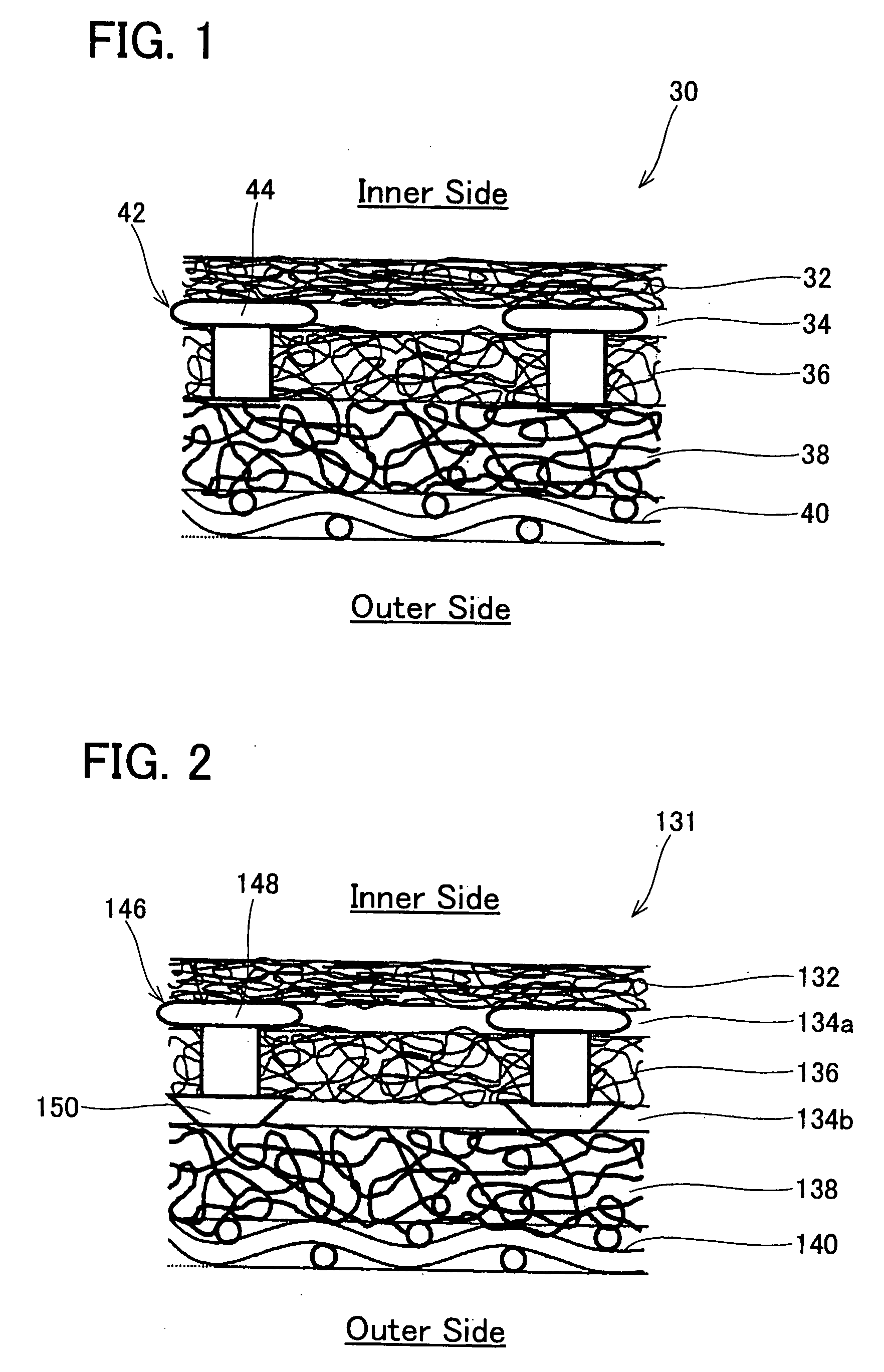
[0025] In this filter, also, foreign matter that has adhered to the surface of the outer filter cloth is prevented from encroaching into pores of the inner filter layer. If the foreign matter that has adhered to the surface of the outer filter cloth tries to encroach into the intermediate filter cloth, this encroachment does not readily occur due to the intermediate filter cloth being formed from woven cloth, and the foreign matter readily peels off the outer filter cloth when the fuel filtering is halted.
[0026] It is preferred that the intermediate filter cloth is formed from woven cloth woven from fibers having a filament diameter of at least 100 μm, and the particle diameter allowed passage thereby is greater than the particle diameter allowed passage by the outer filter cloth. Since the int

Problems solved by technology

As a result, the pores of the outer filter cloth are obstructed by foreign matter that ought to be captured by the inner filter cloth, and consequently neither of the filte

Method used


Image

  • Filter
  • Filter
  • Filter

Examples


Embodiment Construction

[0042] A filter according to a representative embodiment of the present teachings will be described below with reference to figures. The filter may be used as a filter member of a filter device 20 (a suction filter of a fuel pump). As shown in FIG. 9, the filter device 20 is attached to an intake port 18 of a fuel pump 12. The fuel pump 12 is disposed within a fuel tank, and discharges the fuel within the fuel tank to the exterior of the fuel tank.

[0043] The fuel pump 12 has a connector 14 and a discharge port 16. The connector 14 and discharge port 16 are formed at an upper face of the fuel pump 12. The connector 14 is connected with a power supply device (not shown). The power supply device supplies power to the fuel pump 12 via the connector 14. A discharge pipe (not shown) is attached to the discharge port 16. An injector is connected to the other end of the discharge pipe, and fuel is supplied to an engine from the injector.

[0044] The intake port 18 is formed at a lower face ...


PUM

PropertyMeasurementUnit
Diameteraaaaaaaaaa
Particle diameteraaaaaaaaaa

Abstract

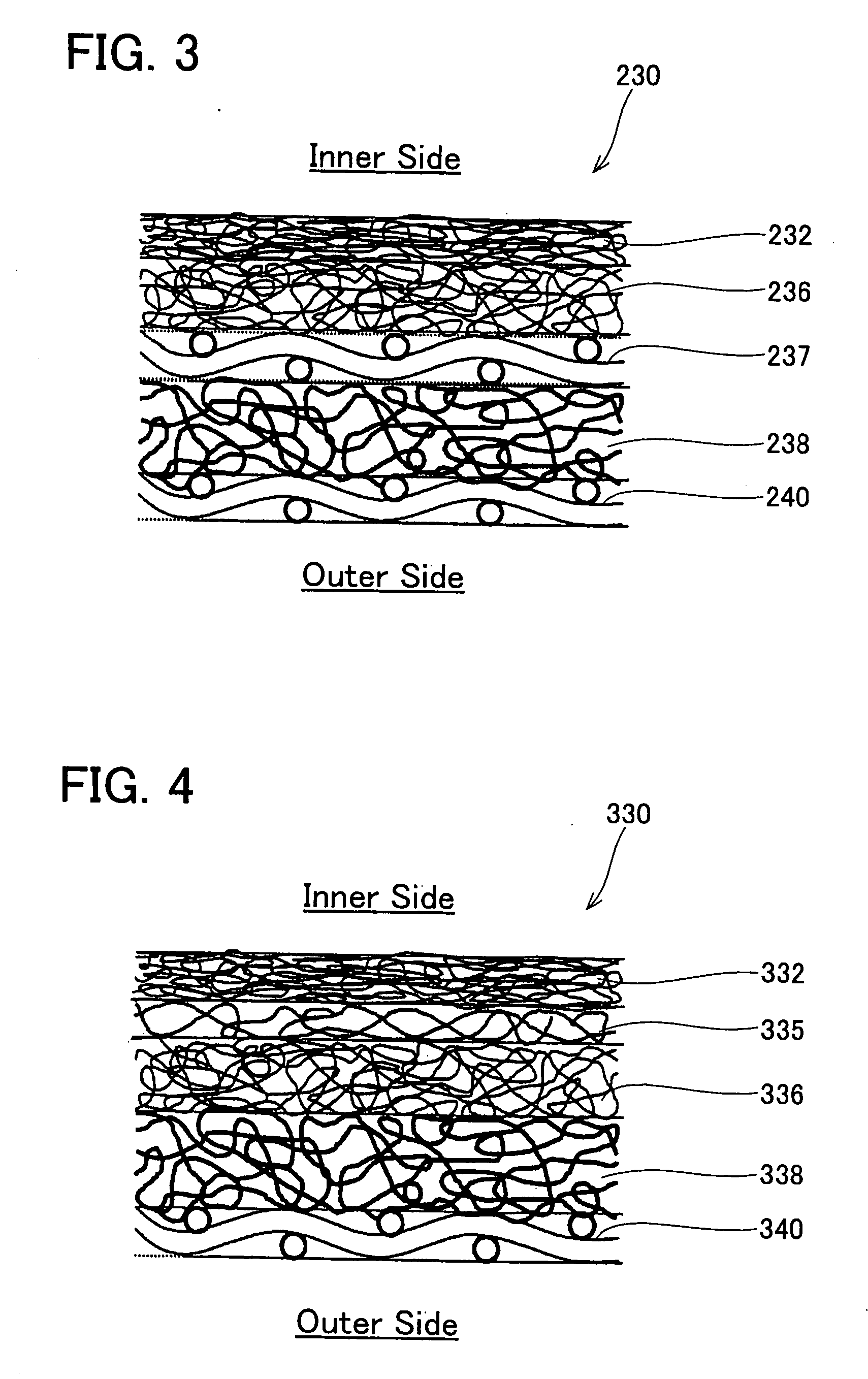
Filter (30) may comprise a first filter cloth (36) and a second filter cloth (32) disposed downstream from the first filter cloth (36). A particle diameter allowed passage by the second filter cloth (32) may be smaller than a particle diameter allowed passage by the first filter cloth (36). A space (34) may be provided between the first filter cloth (36) and the second filter cloth (32), the space (34) allowing the passage of foreign matter having a particle diameter greater than the particle diameter allowed passage by the first filter cloth (36).

Description

CROSS REFERENCE [0001] This application claims priority to Japanese Patent application number 2005-155218, filed on May 27, 2005, the contents of which are hereby incorporated by reference as if fully set forth herein. BACKGROUND OF THE INVENTION [0002] 1. Field of the Invention [0003] The present invention relates to a filter (e.g., a suction filter attached to a fuel intake port of a fuel pump) for removing foreign matter from fuel supplied to an internal combustion engine (e.g., an engine for a motor vehicle). Specifically, it relates to the improvement of a filter having a multi-layered configuration in which a plurality of filter cloths overlap. [0004] 2. Description of the Related Art [0005] Japanese Laid-open Patent Publication No. 2000-246026 discloses a filter for removing foreign matter from fuel supplied to an internal combustion engine. This filter has a structure wherein a plurality of filter cloths overlap. In this filter, a filter cloth at an outermost side (i.e., an ...

Claims


Application Information

Patent Timeline
IPC IPC(8): B01D29/00F02M37/24F02M37/34F02M37/44F02M37/50
CPCB01D29/56F02M37/22B01D35/027B01D29/86F02M37/24F02M37/34F02M37/44F02M37/50
Inventor YOSHIDA, SHIGERUSUZUKI, NOBUO
Owner AISAN IND CO LTD
Learn More