Semiconductor device and method of manufacturing the same
a technology of semiconductor and semiconductor, applied in the direction of semiconductor/solid-state device manufacturing, semiconductor devices, semiconductor devices, etc., can solve the problems of inability to achieve a sufficient increase in mobility, for example, about two times as much, and the innate characteristics of micro-fabrication are prominen
- Summary
- Abstract
- Description
- Claims
- Application Information
AI Technical Summary
Benefits of technology
Problems solved by technology
Method used
Image
Examples
first embodiment
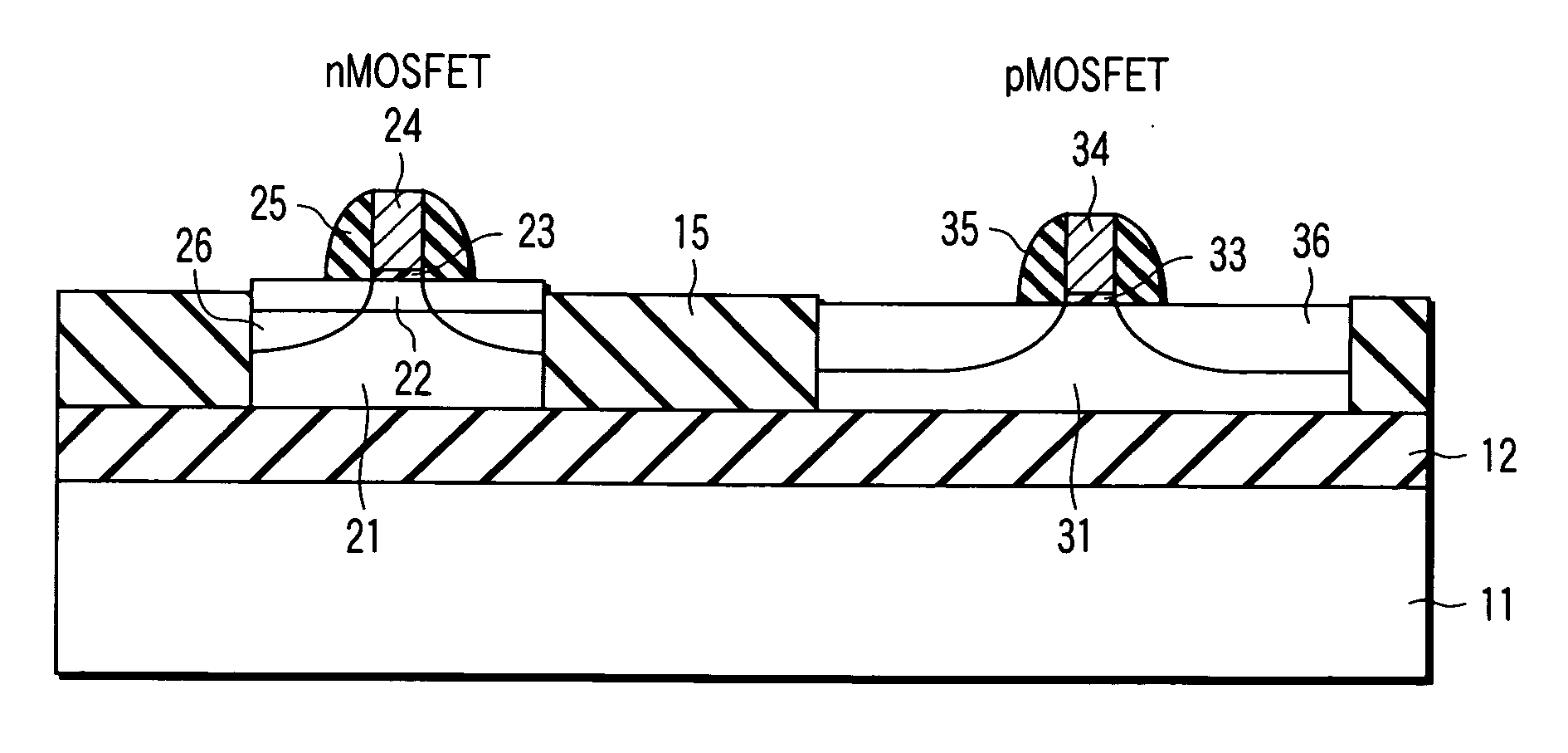
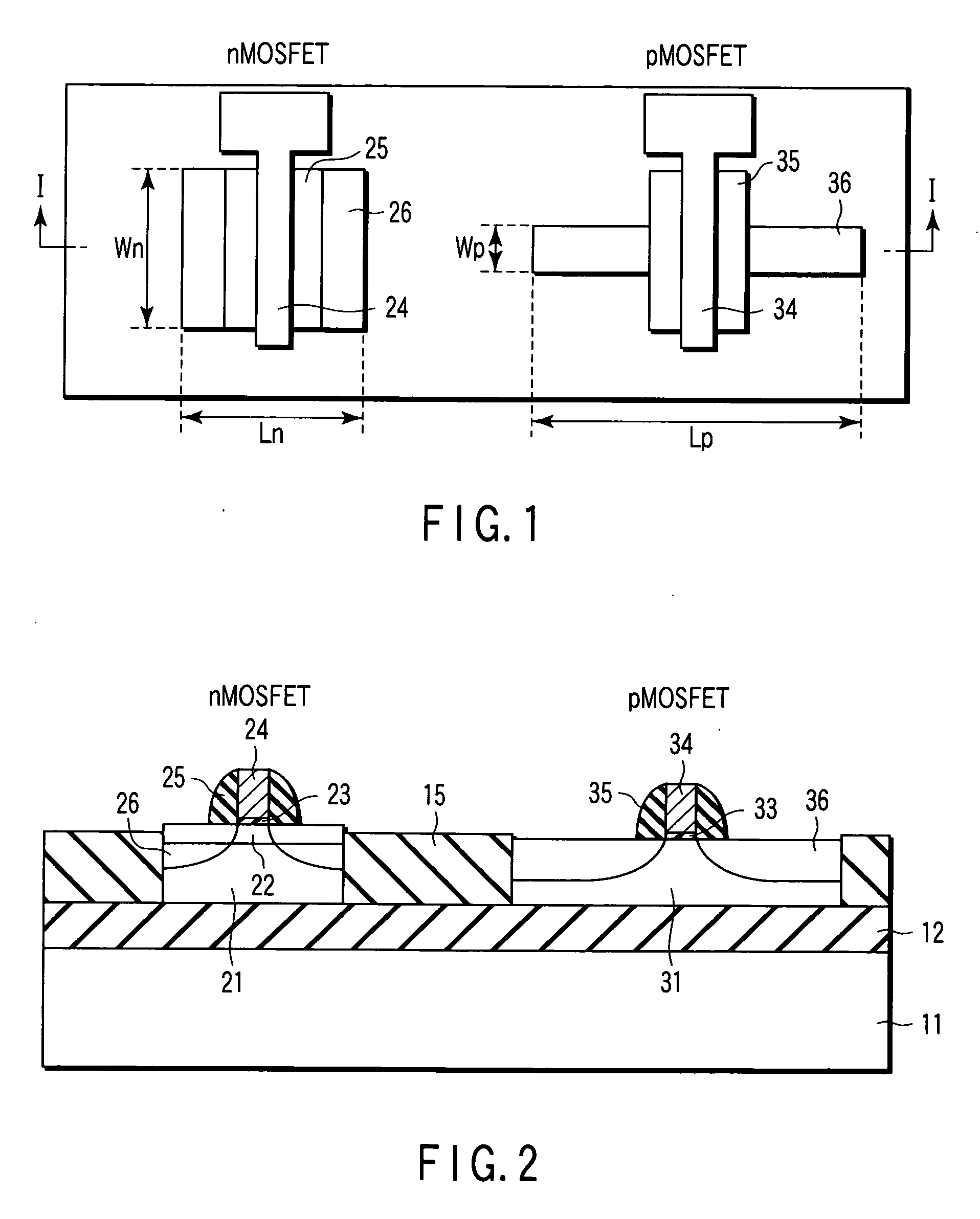
[0072]FIGS. 1 and 2 are diagrams showing a brief structure of a semiconductor device according to the first embodiment of the present invention. FIG. 1 is a plan view of the device, and FIG. 2 is a cross sectional view taken along an arrow I-I shown in FIG. 2.
[0073] As shown in these figures, a Si oxide film (embedded insulating layer) 12 is formed on a Si substrate 11. A lattice-relaxed SiGe layer 21 is formed on a part of the Si oxide film 12, and a strained Si layer 22 is formed on the SiGe layer 21. An nMOSFET is formed on the strained Si layer 22. That is, a gate electrode 24 is formed via a gate insulating film 23 on the strained Si layer 22. A gate sidewall insulating film 25 is formed on each of the sidewalls of the gate electrode 24, and further a source-drain region 26 is formed on the strained Si layer 22.
[0074] A strained SiGe layer 31 is formed on a part of the Si oxide film 12 to interpose an element separation insulating film 15 between the layer 31 itself and the S...
second embodiment
[0091]FIG. 5 is a cross sectional view showing a brief structure of a CMOS-type semiconductor device according to the second embodiment of the present invention. The same structural elements as those shown in FIG. 2 are designated by the same reference numerals, and the detailed explanations are not repeated here. The plan view of this embodiment is substantially the same as that of FIG. 1 described above, and therefore it is omitted.
[0092] The point of this embodiment, which is different from that of the first embodiment is that the pMOSFET is formed not by the strained SiGe layer 31 having uniaxial compression strain in the channel length direction, but by the strained Si layer 32 having uniaxial tensile strain in the channel width direction.
[0093] As in the case of the first embodiment, the channel of the nMOSFET is a strained Si layer 22 having biaxial tensile strain and formed by epitaxial growth on the lattice relaxed SiGe layer 21. On the other hand, the pMOSFET has a struc...
third embodiment
[0101]FIGS. 7 and 8 are diagrams showing a brief structure of a semiconductor device according to the third embodiment of the present invention. FIG. 7 is a plan view of the device, and FIG. 8 is a cross sectional view taken along an arrow I-I shown in FIG. 7. The same structural elements as those shown in FIGS. 1 and 2 are designated by the same reference numerals, and the detailed explanations are not repeated here.
[0102] The point of this embodiment, which is different from that of the first embodiment is that the nMOSFET is formed not by the strained Si layer having biaxial compression strain, but by the strained Si layer 42 having uniaxial tensile strain in the channel width direction.
[0103] That is, the channel of the nMOSFET is made of a strained Si layer 42 having uniaxial tensile strain and formed by epitaxial growth on the strained SiGe layer 41 having uniaxial compression strain. On the other hand, the channel of the pMOSFET is formed of the strained SiGe layer 31 havin...
PUM
 Abstract
Description
Claims
Application Information
 - R&D
- Intellectual Property
- Life Sciences
- Materials
- Tech Scout
- Unparalleled Data Quality
- Higher Quality Content
- 60% Fewer Hallucinations
Browse by: Latest US Patents, China's latest patents, Technical Efficacy Thesaurus, Application Domain, Technology Topic, Popular Technical Reports.
© 2025 PatSnap. All rights reserved.Legal|Privacy policy|Modern Slavery Act Transparency Statement|Sitemap|About US| Contact US: help@patsnap.com


