Liquid sealing type vibration control device

Inactive Publication Date: 2006-11-30
TOYO TIRE & RUBBER CO LTD
View PDF16 Cites 13 Cited by
  • Summary
  • Abstract
  • Description
  • Claims
  • Application Information

AI Technical Summary

Benefits of technology

[0017] In accordance with this invention, it was able to provide such a liquid sealing type vibration control device that enables the top parts of the first ribs to impinge moderately on the surfaces of the lattice members to reduce sufficiently strange sounds.
[0018] Further either where the first ribs are arranged on the surface of the elastic partition membrane so as to be capable of surrounding lattice holes every a given number of the lattice holes and the second ribs are arranged on the surface of the elastic partition membrane in a distributed manner or where the first ribs and the second ribs are arranged on the surface of the elastic partition membrane so as to be capable of surrounding lattice holes every a given number of the lattice holes, in a large amplitude vibration state, it was able to preve

Problems solved by technology

According to the prior art construction above, it is possible to reduce the strange sounds can be reduced to some degree, but the generation of impinging sounds when the e

Method used


Image

  • Liquid sealing type vibration control device
  • Liquid sealing type vibration control device
  • Liquid sealing type vibration control device

Examples


first embodiment

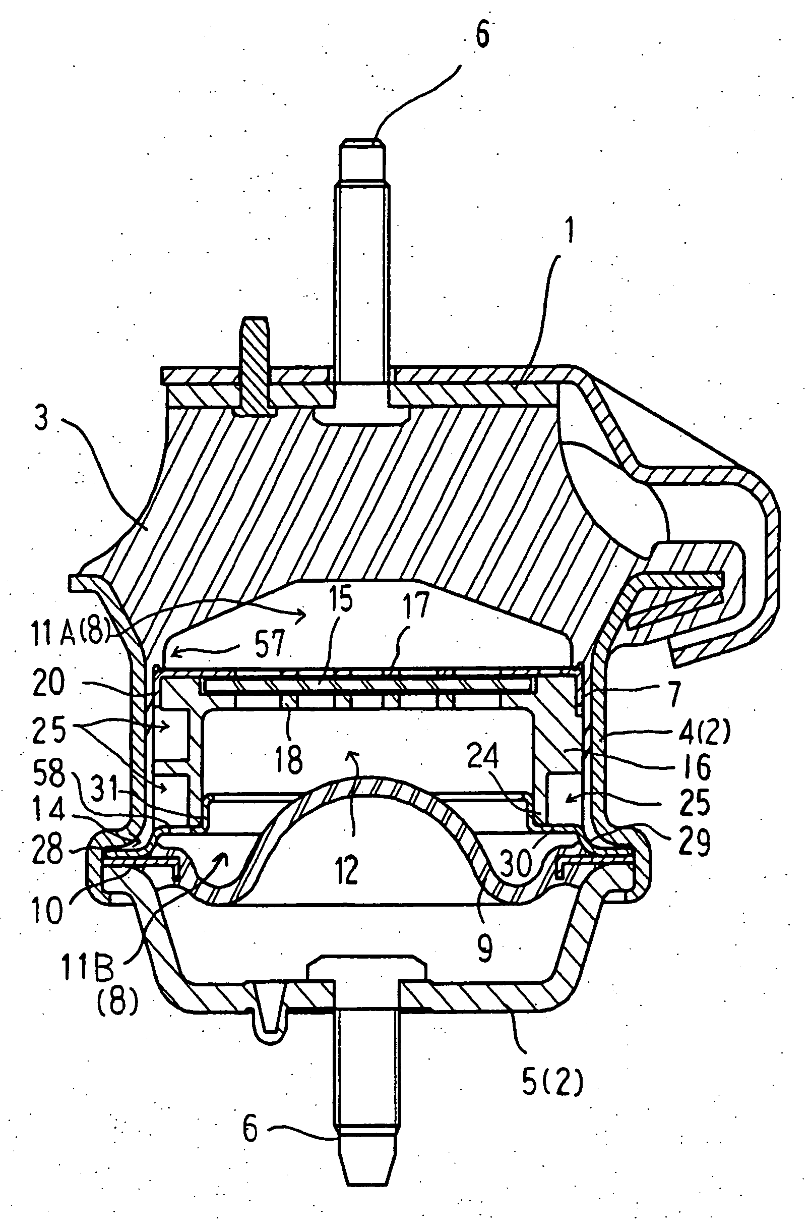
[0034] Now, the embodiment of the invention will be described with reference to the drawings. FIG. 1 indicates the liquid sealing type vibration control device. This vibration control device includes a first attachment fitting 1 to be mounted on an engine of an automobile, a second attachment fitting 2 in a cylindrical form to be mounted on a vehicle body frame beneath the engine, and a vibration isolating base body 3 made of rubber-like elastic material and interconnecting these.

[0035] The first attachment fitting 1 is fashioned in a plate shape and provided with an attachment bolt 6 oriented upwardly. The second attachment fitting 2 includes a cylindrical fitting 4, to which the vibration isolating base body 3 is vulcanization molded, and a cup-shaped bottom fitting 5, in a central part of which a downwardly oriented attachment bolt 6 is provided projectingly.

[0036] The vibration isolating base body 3 is fashioned in a truncated cone shape. And its upper end face and its lower e...

second embodiment

[0047] As shown in FIGS. 12 and 13, it is the structure of the partition body 12 (specifically, the structure of the orifice 25), the structure of the bottom fitting 5, and the structure of the interior of the first liquid chamber 11A that are different from the first embodiment. The other constitution than them is the same as in the first embodiment, and different points of the aforementioned structures will be explained.

12>

[0048] The orifice 25 makes one round about the axis center O of the cylinder member 16. The orifice 25 communicates with the opening of the partition membrane displacement-regulating member 17 through the cutout. And it communicates with the second liquid chamber 11B through the opening 58 of the sandwiching member 14.

5>

[0049] It is tilted at a given angle relative to the axis center of the cylindrical fitting 4.

11A>

[0050] A stirring plate 60 in a disc shape is provided within the first liquid chamber 11A, and a first liquid chamber side orifice 63 is formed...


PUM


Abstract

Provided is a liquid sealing type vibration control device capable of sufficiently reducing strange sounds which comprises a first attachment fitting (1), a second attachment fitting (2), a vibration-isolating base body (3), a diaphragm (9), a partition body (12), and an orifice (25), the partition body (12) including an elastic partition membrane (15) and a pair of lattice members (17, 18). The elastic partition membrane (15) is provided on its both faces with rib groups (50) in a projecting manner, the rib groups (50) each consist of plural first ribs (51) and plural second ribs (52) mingled mutually, the first ribs (51) are set in such a height dimension that their tops can be situated apart from the lattice members (17, 18), and the second ribs (52) are set in such a height dimension that their tops abut on the lattice members (17, 18) and in a smaller rib width than the first ribs (51).

Description

TECHNICAL FIELD [0001] This invention relates to a liquid sealing type vibration control device which comprises a first attachment fitting, a cylindrical second attachment fitting, a vibration isolating base body made of rubber-like elastic material interconnecting these, a diaphragm attached to the second attachment fitting and forming a liquid sealing chamber between the vibration isolating base body and itself, a partition body comparting the liquid sealing chamber into a first liquid chamber on a side of the vibration isolating base body and a second liquid chamber on a side of the diaphragm, and an orifice putting the first liquid chamber and the second liquid chamber into communication with each other, the partition body including an elastic partition membrane and a pair of lattice members regulating a displacement amount of the elastic partition membrane from both sides thereof. BACKGROUND ART [0002] The aforementioned liquid sealing type of vibration control device is instal...

Claims


Application Information

Patent Timeline
IPC IPC(8): F16F13/00F16F13/10
CPCF16F13/106
Inventor HATAKEYAMA, SHINGOITO, MASAAKIEDO, TOMOYOSHI
Owner TOYO TIRE & RUBBER CO LTD
Why Eureka
Try Eureka