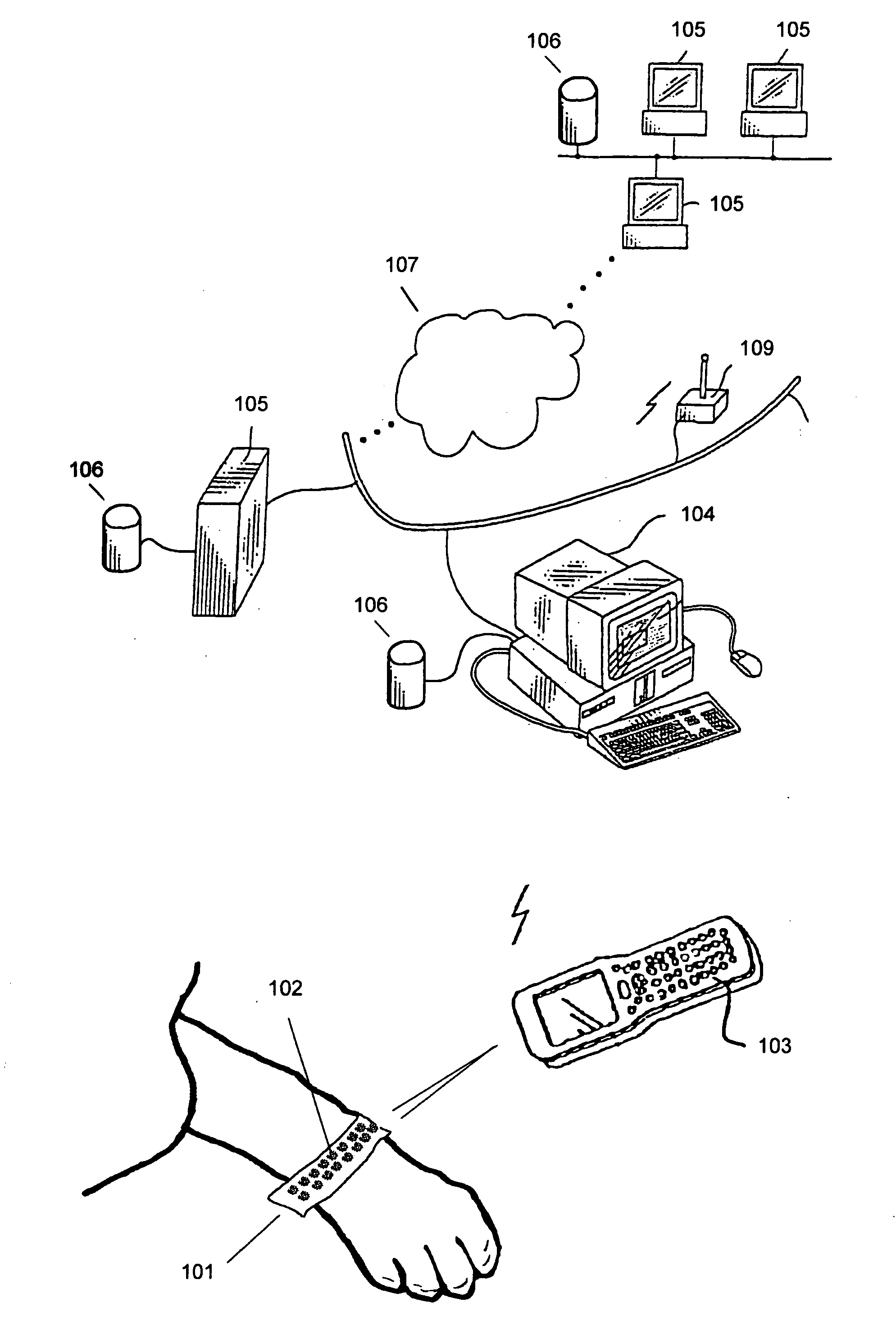
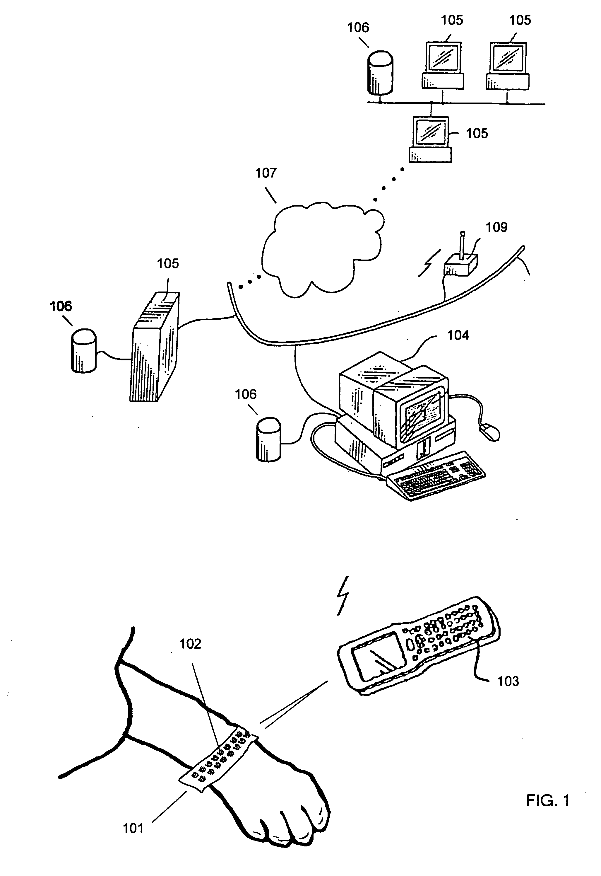
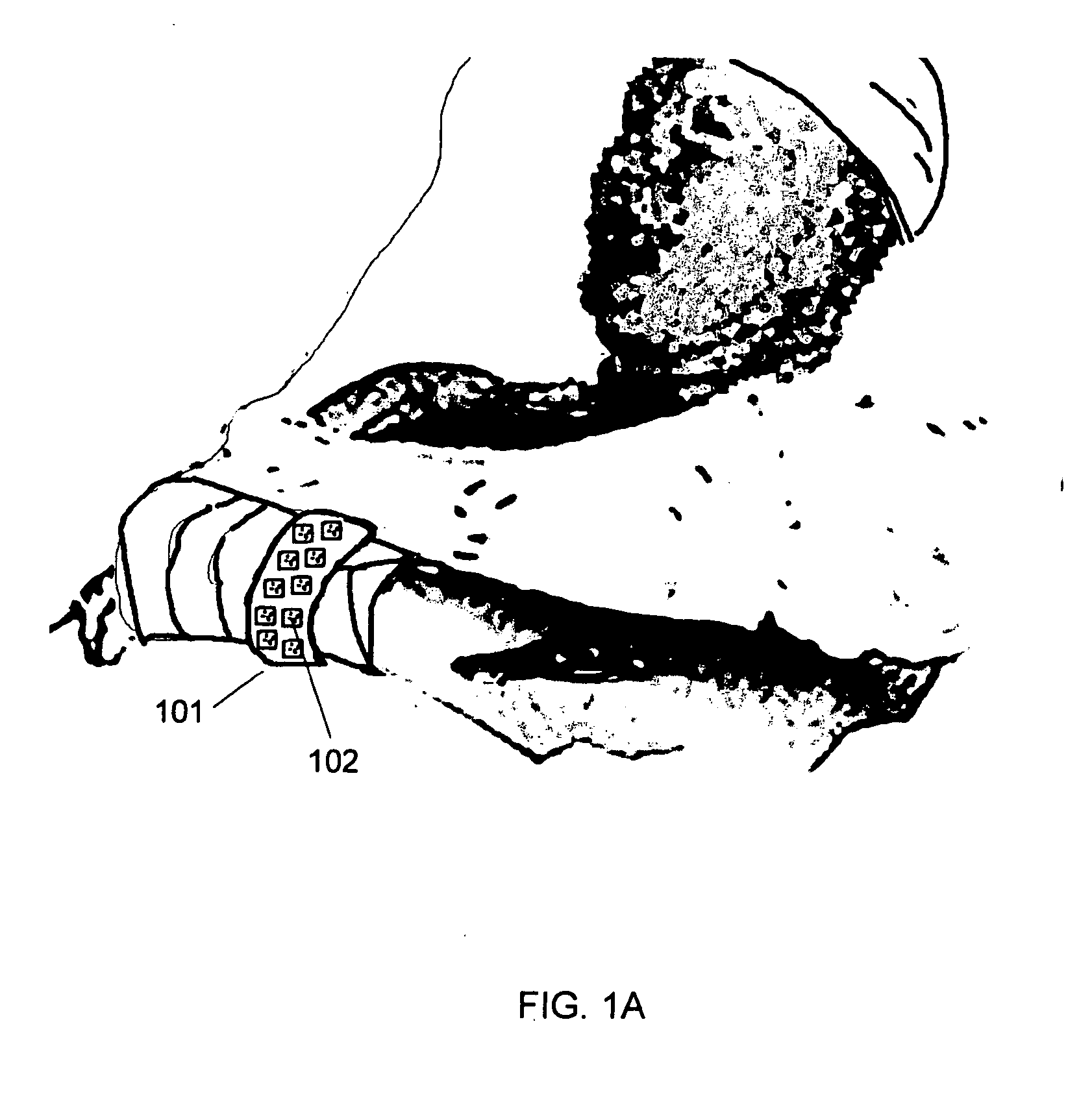
Bar coded wristband

a wristband and bar code technology, applied in the field of bar coded wristbands, can solve problems such as linear bar codes, problems associated with such bar coded wristbands, and problems that can be present,

Active Publication Date: 2006-11-30
HAND HELD PRODS
View PDF56 Cites 129 Cited by
  • Summary
  • Abstract
  • Description
  • Claims
  • Application Information

AI Technical Summary

Problems solved by technology

Unfortunately, there are a series of problems associated with such bar coded wristbands.
Many, if not all of these problems can be present in other institutional bar code wristband applications.
The first problem is that a linear bar code, a series of lines of varying thickness, a pattern familiar to most as similar to a merchandising product UPC code, is difficult to print on a wristband because of the width limitations of most typical bands.
The problem with this bar code wristband arrangement is that the bar code then rolls around the wrist band.
That is a bar code scanner trying to read such a bar code symbol views parts of the code at varying distances that can lead to depth field focus problems for the bar code reader optics package.
Or far worse, some of the code may be wrapped around the limb and not visible to the reader precluding a successful read.
While this solution generally exposes the entire code, thus solving the wrap around problem, such linear bar codes must be printed very small.
If the person to be identified is injured, sleeping, or otherwise immobilized, the task of rotating the wristband can be difficult.
The possible consequences of manually rotating the band range from inconvenience and discomfort to worsening an injury.
Another problem with bar coded wristbands is that the code can become distorted, blurred, or otherwise unreadable.
For example, a person tugging at the wristband or other physical damage to the wris

Method used


Image

  • Bar coded wristband
  • Bar coded wristband
  • Bar coded wristband

Examples


example 1

[0095]FIG. 8 shows an inventive wristband 101 with multiple 11.7 mil MicroPDF417 2 D bar codes 102. In addition to the multiple 2 D bar codes, there is a small break for human readable information. In practice such breaks should be minimized in order to preserve the high likelihood that a symbol will be in view for a bar code reader without needing to manipulate the wristband.

example 2

[0096]FIG. 9 shows an inventive wristband 101 with multiple 11.7 mil Truncated PDF417 2 D bar codes 102. Again, In addition to the multiple 2 D bar codes, there is a small break for human readable information. In practice such breaks should be minimized in order to preserve the high likelihood that a symbol will be in view for a bar code reader without needing to manipulate the wristband.

example 3

[0097]FIG. 10 shows an inventive wristband 101 with two offset rows of multiple Aztec symbols 102. In addition to the multiple 2 D bar codes 102, there is a small break for human readable information. In practice, even small breaks should still be minimized in order to preserve the high likelihood that a symbol will be in view for a bar code reader without needing to manipulate the wristband. A single row of Aztec symbols continues without break under the human readable information.


PUM


Abstract

A bar coded patient wristband identifies a patient wearing the wristband. The system comprises a bar code reader to read the bar coded wristband. A host computer is connected to the digital link to receive the segment of data from the bar code reader. A database correlates the segment of data to a patient to identify the patient. The patient wristband comprises a plurality of bar code symbols. A computer then retrieves a patient record from the database to identify the patient wearing the wristband. In one embodiment, a patient wristband for identifying a patient accepts a plurality of markings of 2 D bar codes distributed along the strip. In another embodiment, the wristband comprises a plurality of linear bar code lines and spaces distributed along the strip. The lines and spaces form a 1 D bar code.

Description

CROSS REFERENCE [0001] This application claims priority under 35 U.S.C. §119 of Provisional Application No. 60 / 685,861, filed May 31, 2005 entitled “Improved Bar Coded Wristband.” The priority of the above application is claimed and the disclosure of the above application is incorporated herein by reference in its entirety.FIELD OF THE INVENTION [0002] This invention relates generally to bar coded wristbands and more particularly to a system and method for reading bar coded wristbands without disturbing the wearer of the wristband. BACKGROUND OF THE INVENTION [0003] Wristbands can be used to identify individual persons wearing them. Typically wristbands have been cut from paper, plastic, or other bendable sheet type of material in the form of a strip. The strip can then be rolled to encircle a limb of the person, most typically the individual's wrist. Various fasteners or adhesives can be applied to maintain the physical presence of the wristband on the person. Techniques for fasten...

Claims


Application Information

Patent Timeline
IPC IPC(8): G08B26/00
CPCA61B5/117G09F3/005G08B21/22A61B5/411
Inventor HUSSEY, ROBERT M.HAVENS, WILLIAM H.
Owner HAND HELD PRODS
Why Eureka
Try Eureka