Eureka AIR delivers breakthrough ideas for toughest innovation challenges, trusted by R&D personnel around the world.

Robust data transmission using broadcast digital television signals

a technology of digital television and data transmission, applied in the direction of color television with bandwidth reduction, television system, instruments, etc., can solve the problem that the television infrastructure is not always suited to these types of data, and achieve the effect of reducing the signal-to-noise ratio

Inactive Publication Date: 2006-05-09
TRUE POSITION INC
View PDF18 Cites 161 Cited by
  • Summary
  • Abstract
  • Description
  • Claims
  • Application Information

AI Technical Summary

Benefits of technology

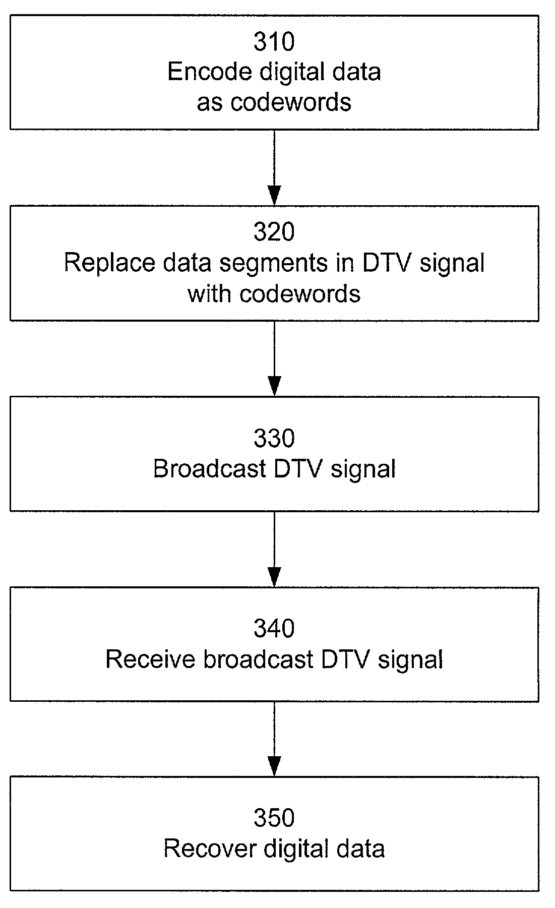
[0011]In accordance with the present invention, digital data is transmitted as part of a digital television (DTV) broadcast signal by encoding the digital data as codewords and replacing some of the data segments in the DTV signal with the codewords. The use of long codewords results in a transmission which is more robust than the portions of the DTV broadcast signal used for television programming and can therefore be received at lower signal to noise ratios. The use of a finite set of codewords allows recovery of the digital data using a simple bank of correlators at the receiver.
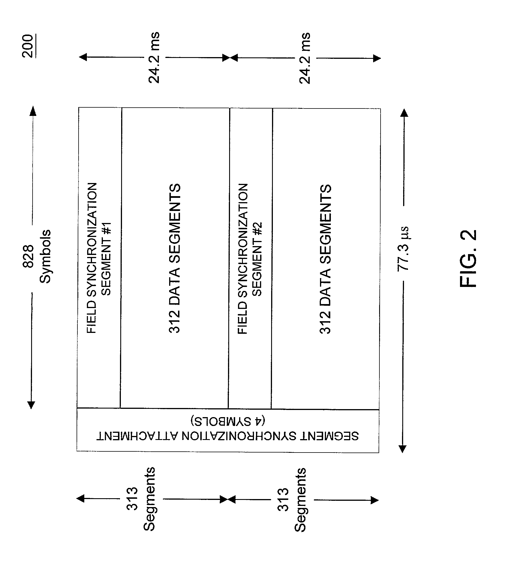
[0013]In one implementation, the digital data is encoded into codewords as follows. The digital data is divided into bit sequences. Each bit sequence is encoded as a corresponding codeword which is selected from a finite set of codewords. In one embodiment, the bit sequences are all the same length, the codewords are all the same length and are all orthogonal to each other, and the codewords are longer than the bit sequences. For example, the digital data may be divided into 3-bit sequences, with a different codeword assigned to each of the eight possible 3-bit sequences. Furthermore, each codeword may be the same length as a full data segment (i.e., 828 symbols in the ATSC standard), thus resulting in a much more robust data transmission system compared to the television programming data contained in the DTV signal.

Problems solved by technology

The television infrastructure is not always suited for these types of data.

Method used


Image

  • Robust data transmission using broadcast digital television signals
  • Robust data transmission using broadcast digital television signals
  • Robust data transmission using broadcast digital television signals

Examples


Embodiment Construction

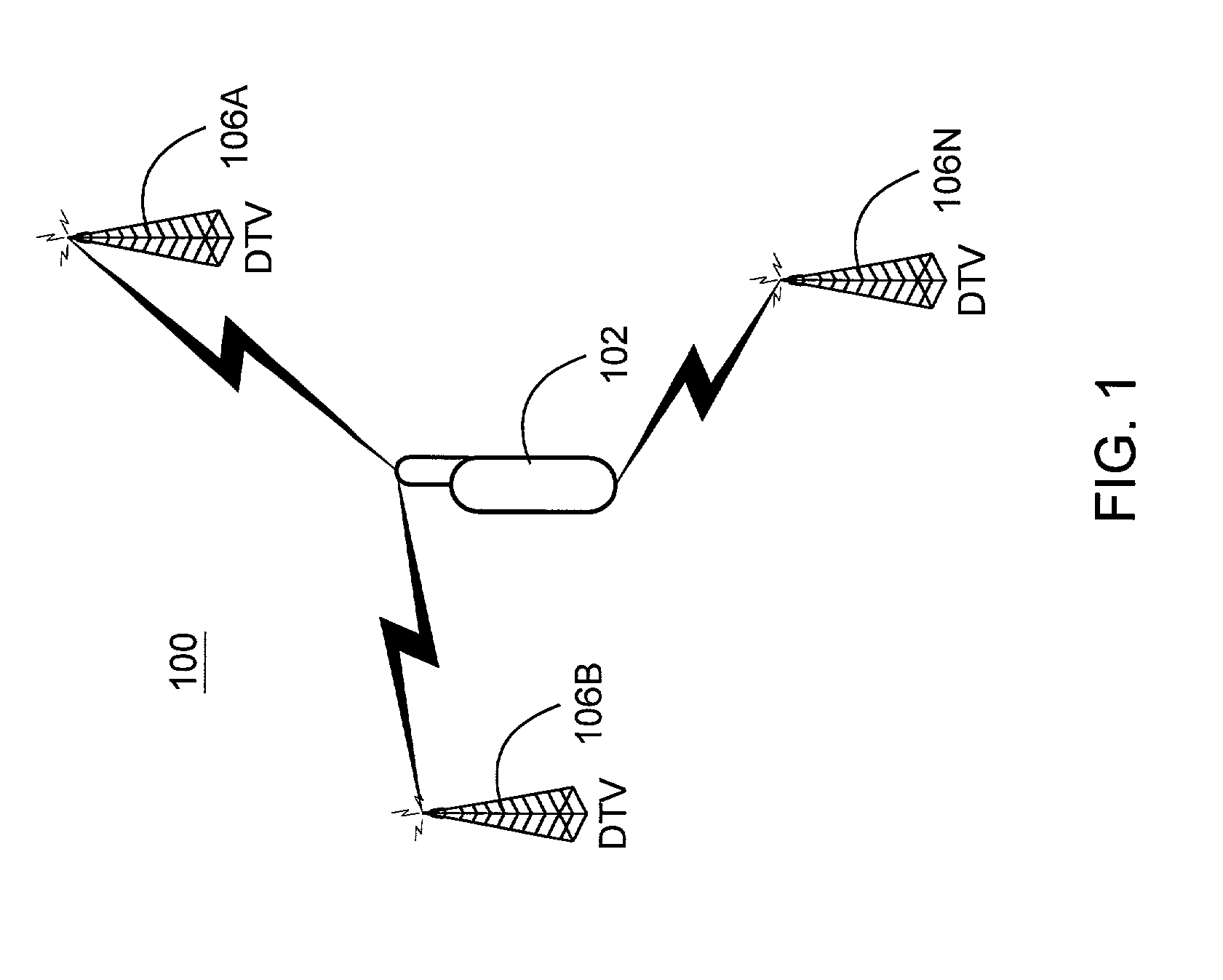
[0033]FIG. 1 is a block diagram of an example system 100 according to the present invention. System 100 includes a receiver 102 that receives digital television (DTV) broadcasts from one or more DTV transmitters 106A–N.

[0034]One example of a DTV transmitter 106 is a transmission tower which broadcasts DTV signals over the air to receiver 102. Another example is the transmitter for a cable television system, in which case the DTV signals arrive at the receiver 102 via a cable link. Satellite TV systems, also known as Direct Broadcast Satellites (DBS), are another example of digital TV broadcast systems. For example, EchoStar and DirecTV are the primary DBS services in the U.S. market. Generally speaking, there currently are three basic types of commercial digital TV broadcast systems: terrestrial, cable, and satellite. Satellite TV systems are all digital; whereas cable and terrestrial systems are converting to digital from their mostly analog predecessors. These digital TV systems u...


PUM


Abstract

A DTV signal includes frames, and the frames include data segments. Data segments are replaced by codewords which represent digital data. The DTV signals are broadcast and received by receivers. The receivers recover the digital data from the codewords in the DTV signals, for example by using matched filtering. By using long codewords, the digital data can be broadcast over a longer range and recovered by simpler circuitry in comparison to the television programming contained in the DTV signal. In one implementation, the DTV signal is an American Television Standards Committee (ATSC) DTV signal.

Description

CROSS-REFERENCE TO RELATED APPLICATION[0001]This application claims priority under 35 U.S.C. 119(e) from U.S. Provisional Patent Application Ser. No. 60 / 281,269, “An ATSC Standard DTV Channel for Low Data Rate Broadcast to Mobile Receivers,” by James J. Spilker and Matthew Rabinowitz, filed Apr. 3, 2001, which subject matter is incorporated herein by reference.BACKGROUND OF THE INVENTION[0002]1. Field of the Invention[0003]This invention relates generally to the transmission of data via broadcast digital television signals, for example digital television signals which follow the American Television Standards Committee (ATSC) format.[0004]2. Description of the Related Art[0005]Starting with the first ATSC standard digital television broadcast in the late 1990's, digital television broadcasting is rapidly expanding in the United States. By the end of 2000, more than 166 digital television transmitters were in operation. The FCC has set a goal that by 2006 all television broadcasting w...

Claims


Application Information

Patent Timeline
IPC IPC(8): H04N7/12H04N11/02G01S1/00G01S5/02G01S19/46H04N7/08H04N7/081H04N21/235H04N21/258H04N21/2662H04N21/2668H04N21/414H04N21/435H04N21/61H04N21/81
CPCG01S5/021G01S5/0215H04N21/235H04N21/25841H04N21/8126H04N21/2668H04N21/41422H04N21/435H04N21/615H04N21/2662A63F2300/205H04N7/12
Inventor OMURA, JIMMY KSPILKER, JR., JAMES JRABINOWITZ, MATTHEW
Owner TRUE POSITION INC
Why Eureka
Eureka Blog
Learn More