Fabrication and packaging of suspended microchannel detectors

Inactive Publication Date: 2005-03-24
MASSACHUSETTS INST OF TECH
View PDF14 Cites 53 Cited by
  • Summary
  • Abstract
  • Description
  • Claims
  • Application Information

AI Technical Summary

Benefits of technology

[0017] The packaging methods of the invention allow for the microfluidic channels to be in a controlled environment and allow the microfluidic channels of the device to be connected to larger sample fluid channels. In addition, the packaging meth

Problems solved by technology

One disadvantage of a cantilever microfluidic channel is that the sample fluid must enter and exit th

Method used


Image

  • Fabrication and packaging of suspended microchannel detectors
  • Fabrication and packaging of suspended microchannel detectors
  • Fabrication and packaging of suspended microchannel detectors

Examples


examples

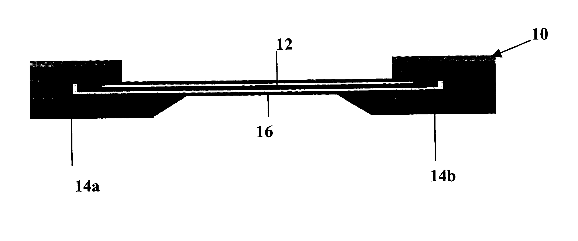
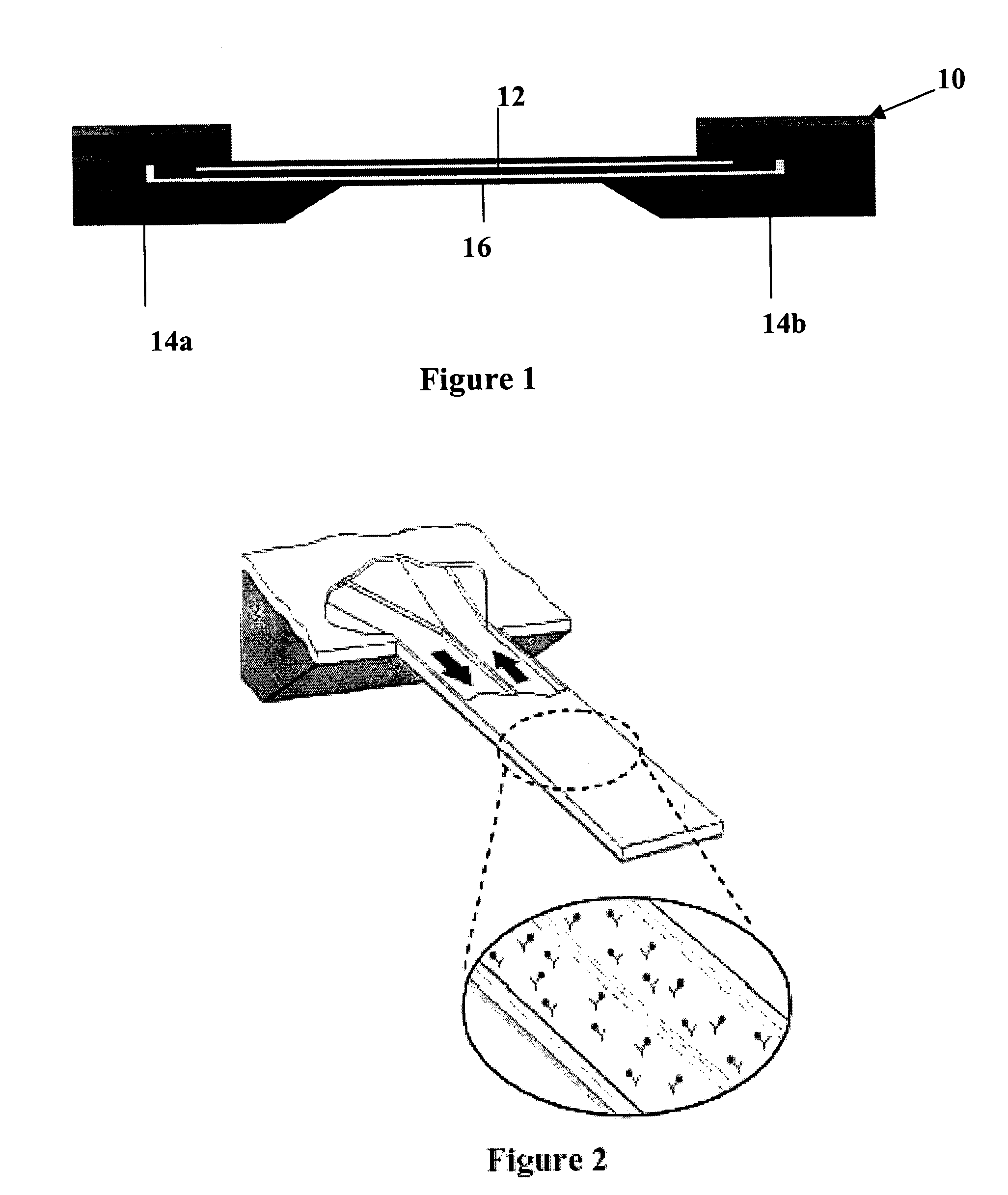
[0074] As described above, suspended microchannels for molecular detection must be sufficiently thin, and additionally they must be configured for continuous fluidic delivery for real-time measurements. To address both of these requirements, we combined a polysilicon Damascene process, sacrificial layer etching in hot potassium hydroxide, and bulk micromachining to fabricate suspended microchannels with a wall thickness of 800 nm and a fluid layer thickness of 1.2 μm. First, we etched microfluidic trenches in a standard silicon wafer using photolithography and reactive ion etching (RIE). The wafer was subsequently coated with 800 nm low-stress low-pressure chemical vapor deposited silicon nitride and followed by a 1.5 μm layer of polysilicon. The polysilicon layer was planarized with chemical mechanical polishing (CMP). The CMP process was timed to stop as soon as it reaches the silicon nitride layer so that the trenches remain filled with polysilicon. After the CMP, a second layer ...


PUM

PropertyMeasurementUnit
Thicknessaaaaaaaaaa
Thicknessaaaaaaaaaa
Thicknessaaaaaaaaaa

Abstract

An apparatus for detecting an analyte in solution that has a suspended beam containing at least one microfluidic channel containing a capture ligand that bonds to or reacts with an analyte. The apparatus also includes at least one detector for measuring a change in the beam upon binding or reaction of the analyte. A method of making the suspended microfluidic channels is disclosed, as well as, a method of integrating the microfluidic device with conventional microfluidics having larger sample fluid channels.

Description

GOVERNMENT SUPPORT [0001] The work described herein was supported, in part, by grants from the Defense Advanced Research Projects Agency (DARPA) (MDA972-001-1-003). The United States government may have certain rights in the invention.BACKGROUND [0002] Conventional procedures based on two-dimensional gel electrophoresis for profiling the concentrations of specific proteins and their byproducts are time-consuming, labor-intensive, and require significant technical expertise to obtain quantitative information. One approach for circumventing these limitations is to develop the equivalent of a DNA microarray for proteins. Protein microarrays consist of various types of capture ligands that exhibit a high binding affinity toward a particular protein. Target proteins are either labeled with a fluorescent label, or additional fluorescently labeled protein is used to selectively bind to the target once it has been capture to a specific site on the array. The latter approach, often referred ...

Claims


Application Information

Patent Timeline
IPC IPC(8): B01L3/00C12M1/00C12M1/12G01N33/543
CPCB01L3/5027B01L3/502707B01L2200/12B01L2300/0627B01L2400/0421G01N33/54373B81B7/007B81B2201/0214B81C1/00071B81C1/00206B81B7/0061H01L2224/48091H01L2224/48465H01L2924/00014H01L2924/00
Inventor MANALIS, SCOTTBURG, THOMAS
Owner MASSACHUSETTS INST OF TECH
Why Eureka
Try Eureka