Imaging lens system

Active Publication Date: 2006-11-30
ENPLAS
View PDF3 Cites 0 Cited by
  • Summary
  • Abstract
  • Description
  • Claims
  • Application Information

AI Technical Summary

Benefits of technology

[0043] Further, in addition to the effects of the imaging lens system according to the first aspect, the imaging lens system according to the second aspect can achieve an imaging lens system that is more reduced in size and weight and has more excellent productivity.
[0044] Furthermore, in addition to the effects of the imaging lens system according to the first or second aspect, the imaging lens system according to the third aspect can achieve a small-size imaging lens system with more excellent optical performance in which the chromatic aberration is more excellently corrected.
[0045] Moreover, in addition to the effects of the first-third aspects, the imaging lens system according to the fourth aspect can achieve an imaging lens system that is more reduced in size and weight and more excellent in the optical performance and the productivity.
[0046] Further, in addition to the effects

Problems solved by technology

However, the lens systems belonging to those types 1-3 have the following problems.
Thus, it is not possible to achieve both the high telecentricity and back focus distance at the same time.
In the lens system belonging to Type 3, it is difficult to well-correct such axia

Method used


Image

  • Imaging lens system
  • Imaging lens system
  • Imaging lens system

Examples


Example

First Example

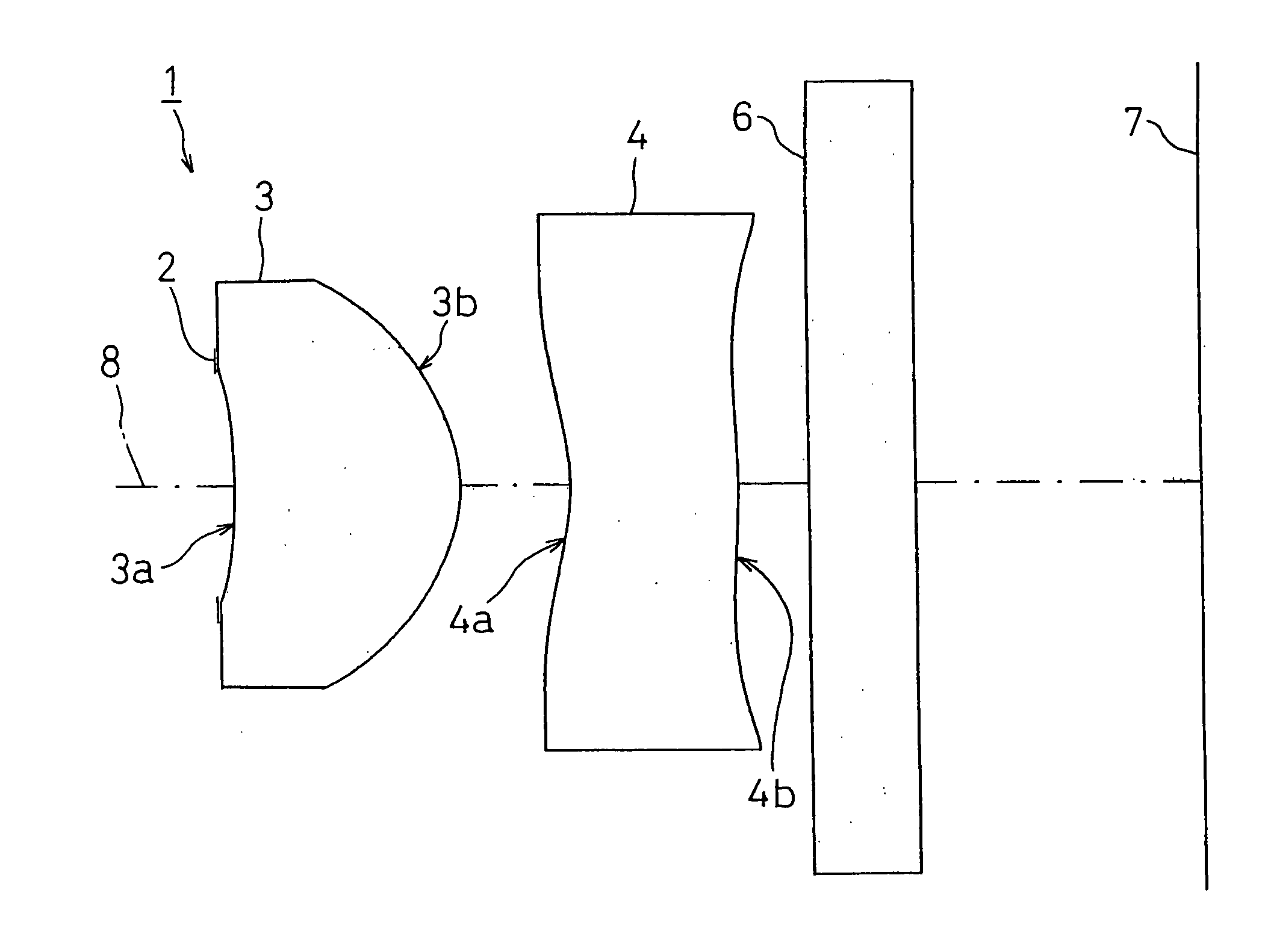
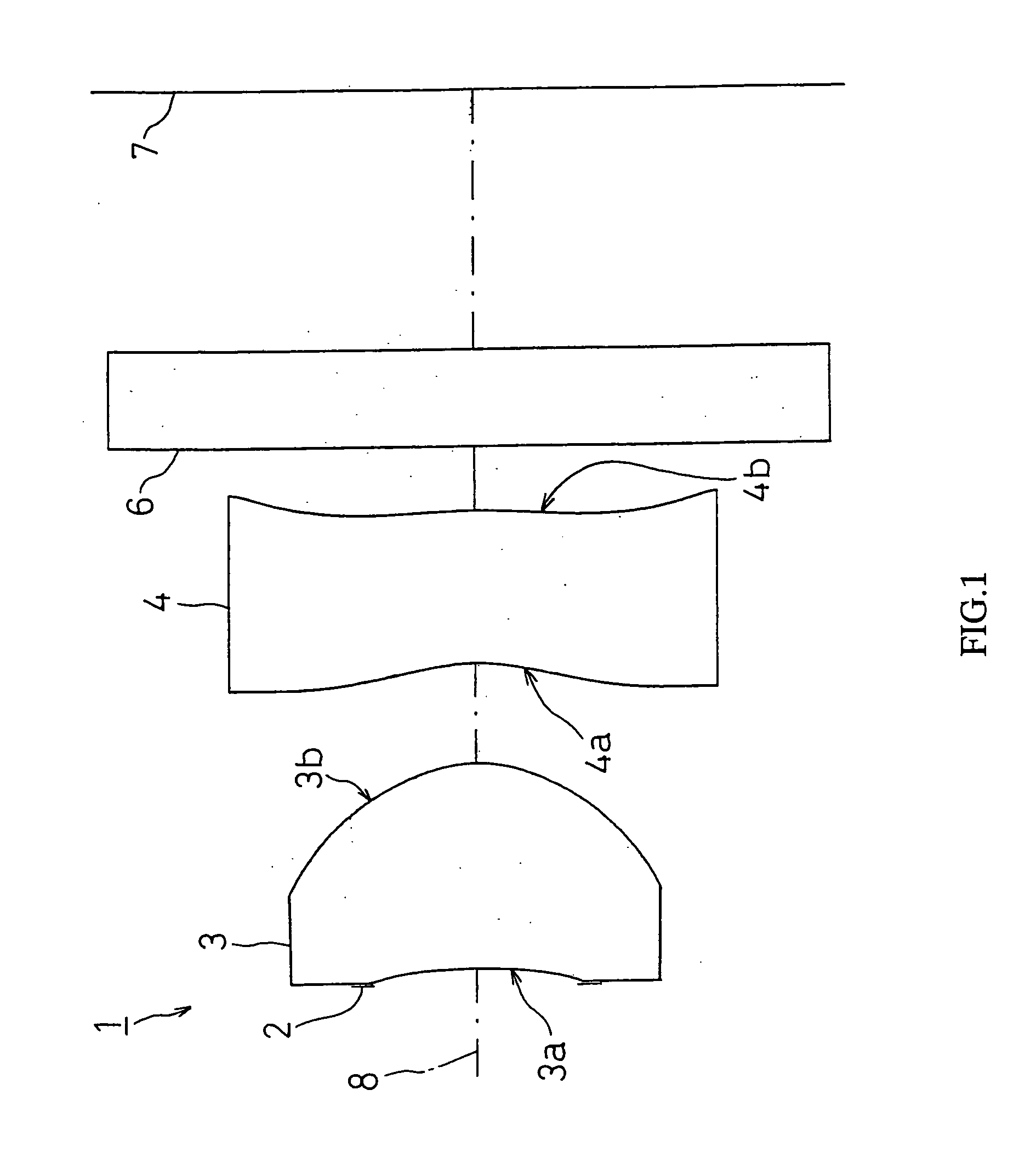
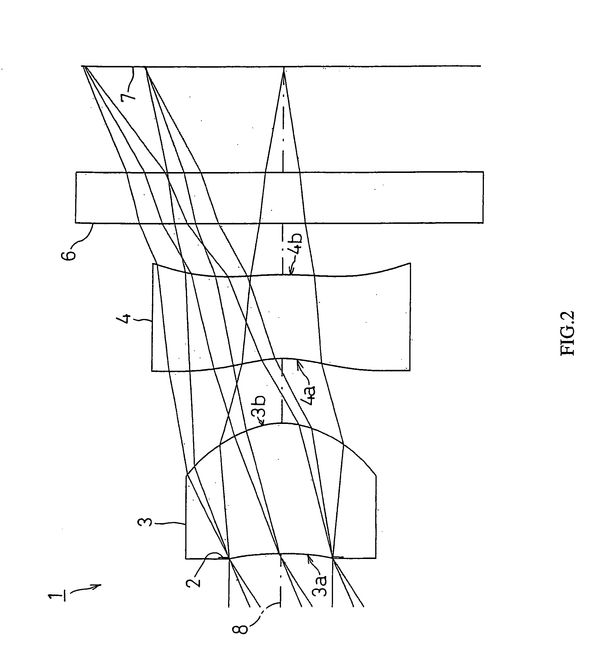
[0133]FIG. 2 shows FIRST EXAMPLE of the present invention. In FIRST EXAMPLE, like the imaging lens system 1 with the structure of FIG. 1, a diaphragm 2 was disposed on the object side of the first face 3a of the first lens 3, and a cover glass as a filter 6 is disposed between the second face 4b of the second lens 4 and an image taking surface 7.

[0134] The imaging lens system 1 of FIRST EXAMPLE was set under the following condition.

Lens Data

[0135] L=2.766 mm, fl=1.803 mm, f1=0.99 mm, f2=−2.02 mm, d1=0.762 mm, d2=0.377 mm, d3=0.482 mm, r1=−2.272 mm, r2=−0.480 mm, r3=−0.700 mm, r4=−2.145 mm, D=1.651, S=0.02, Bfl=1.115, F no=2.85 Face Number(Object Point)rdndvd1 (Diaphragm)∞0.0202 (First Face of First Lens)−2.2720.7621.53156.03 (Second Face of First Lens)−0.4800.3774 (First Face of Second Lens)−0.7000.4921.58530.05 (Second Face of Second Lens)−2.1450.3006 (First Face of Cover Glass)∞0.3001.51664.07 (Second Face of Cover Glass)∞  (Image surface)

[0136]FaceNumberkABCD20....

Example

Second Example

[0140]FIG. 4 shows SECOND EXAMPLE of the present invention. In SECOND EXAMPLE, like the imaging lens system 1 with the structure shown in FIG. 1, a diaphragm 2 was disposed on the object side of the first face 3a of the first lens 3, and a cover glass as a filter 6 is disposed between the second face 4b of the second lens 4 and the image taking surface 7.

[0141] The imaging lens system 1 of SECOND EXAMPLE was set under the following condition.

Lens Data

[0142] L=2.746 mm, fl=1.798 mm, f1=1 mm, f2=−2.01 mm, d1=0.761 mm, d2=0.384 mm, d3=0.486 mm, r1=−2.355 mm, r2=−0.483 mm, r3=−0.700 mm, r4=−2.145 mm, D=1.651, S=0.02, Bfl=1.095, F no=2.85 Face Number(Object Point)rdndvd1 (Diaphragm)∞0.0202 (First Face of First Lens)−2.3550.7611.53156.03 (Second Face of First Lens)−0.4830.3844 (First Face of Second Lens)−0.7000.4861.58530.05 (Second Face of Second Lens)−2.1450.2006 (First Face of Cover Glass)∞0.3001.51664.07 (Second Face of Cover Glass)∞  (Image surface)

[0143]Face Numbe...

Example

Third Example

[0147]FIG. 6 shows THIRD EXAMPLE of the present invention. In THIRD EXAMPLE, like the imaging lens system 1 with the structure shown in FIG. 1, a diaphragm 2 was disposed on the object side of the first face 3a of the first lens 3, and a cover glass as a filter 6 is disposed between the second face 4b of the second lens 4 and the image taking surface 7.

[0148] The imaging lens system 1 of THIRD EXAMPLE was set under the following condition.

Lens Data

[0149] L=2.739 mm, fl=1.805 mm, f1=0.98 mm, f2=−2.04 mm, d1=0.671 mm, d2=0.361 mm, d3=0.534 mm, r1=−1.984 mm, r2=−0.464 mm, r3=−0.700 mm, r4=−2.145 mm, D=1.616, S=0.05, Bfl=1.123, F no=2.85 Face Number(Object Point)rdndvd1 (Diaphragm)∞0.0502 (First Face of First Lens)−1.9840.6711.53156.03 (Second Face of First Lens)−0.4640.3614 (First Face of Second Lens)−0.7000.5341.58530.05 (Second Face of Second Lens)−2.1450.2006 (First Face of Cover Glass)∞0.3001.51664.07 (Second Face of Cover Glass)∞  (Image surface)

[0150]Face Number...


PUM


Abstract

It is to provide an imaging lens system which, while reduced in size and weight, can fully meet the demand for more improvement in the optical performance and also improvement in the productivity. The imaging lens system comprises, in order from an object side towards an image surface side, a diaphragm, a first lens which is a meniscus lens having a positive power whose concave surface facing the object side, and a second lens which is a meniscus lens having a negative power whose convex surface facing the image surface side, wherein the Abbe number of the second lens is set smaller than the Abbe number of the first lens.

Description

BACKGROUND OF THE INVENTION [0001] 1. Field of the Invention [0002] The present invention relates to an imaging lens system and, particularly, to an imaging system of two-lens structure, which is capable of reducing the size and weight and improving the optical performance and productivity. The imaging system is used for an image-taking device that forms images of objects such as scenery and human figures on an image taking surface of a solid image sensor element such as a CCD, CMOS, etc., which is mounted on a portable computer, a television telephone, a cellular phone, and the like. [0003] 2. Description of the Related Art [0004] Recently, there has been an increasing demand for reducing the size and weight and improving the optical performance (high resolution of the solid image sensor element, etc) of an image-taking device (camera) that utilizes a solid image sensor element such as a CCD, CMOS, or the like, which is mounted on a portable telephone, a portable computer, and a te...

Claims


Application Information

Patent Timeline
IPC IPC(8): G02B9/04
CPCG02B13/003G02B9/10G02B3/00
Inventor SAITO, TOMOHIRO
Owner ENPLAS
Why Eureka
Try Eureka