Surface light source device

Inactive Publication Date: 2006-11-30
TOMOEGAWA CO LTD
View PDF9 Cites 60 Cited by
  • Summary
  • Abstract
  • Description
  • Claims
  • Application Information

AI Technical Summary

Benefits of technology

[0007] Having made a detailed study of this problem, the inventors have been able to discover that it can be resolved by positioning a light-diffusing film with directionality beside the light-outputting surface of said light guide. Directionality refers to the fact that

Problems solved by technology

However even in this case, the difficulty remains that light output from the point light source, light-emitting diode 11, has the directionality shown in FIG. 3, and so although portions centered on the light from the central part output laterally from point light source 11 in FIG. 4(b) are bright, the four corners are dark, the upper left and bottom left corners particularly so.
However, with the surface light source device shown in FIG. 1 or the surface light source device shown in FIG. 2, the direction

Method used


Image

  • Surface light source device
  • Surface light source device
  • Surface light source device

Examples


embodiment 1

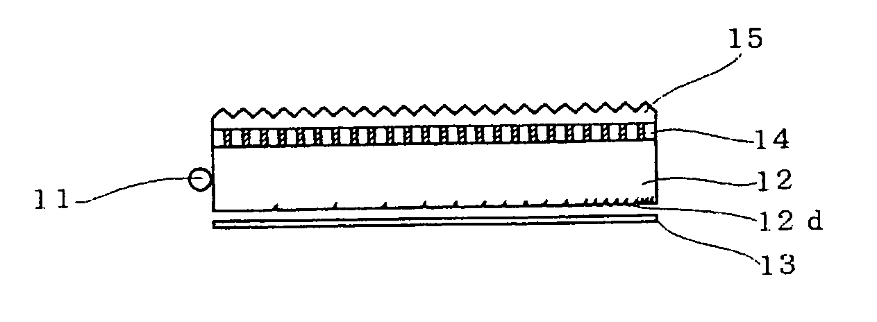
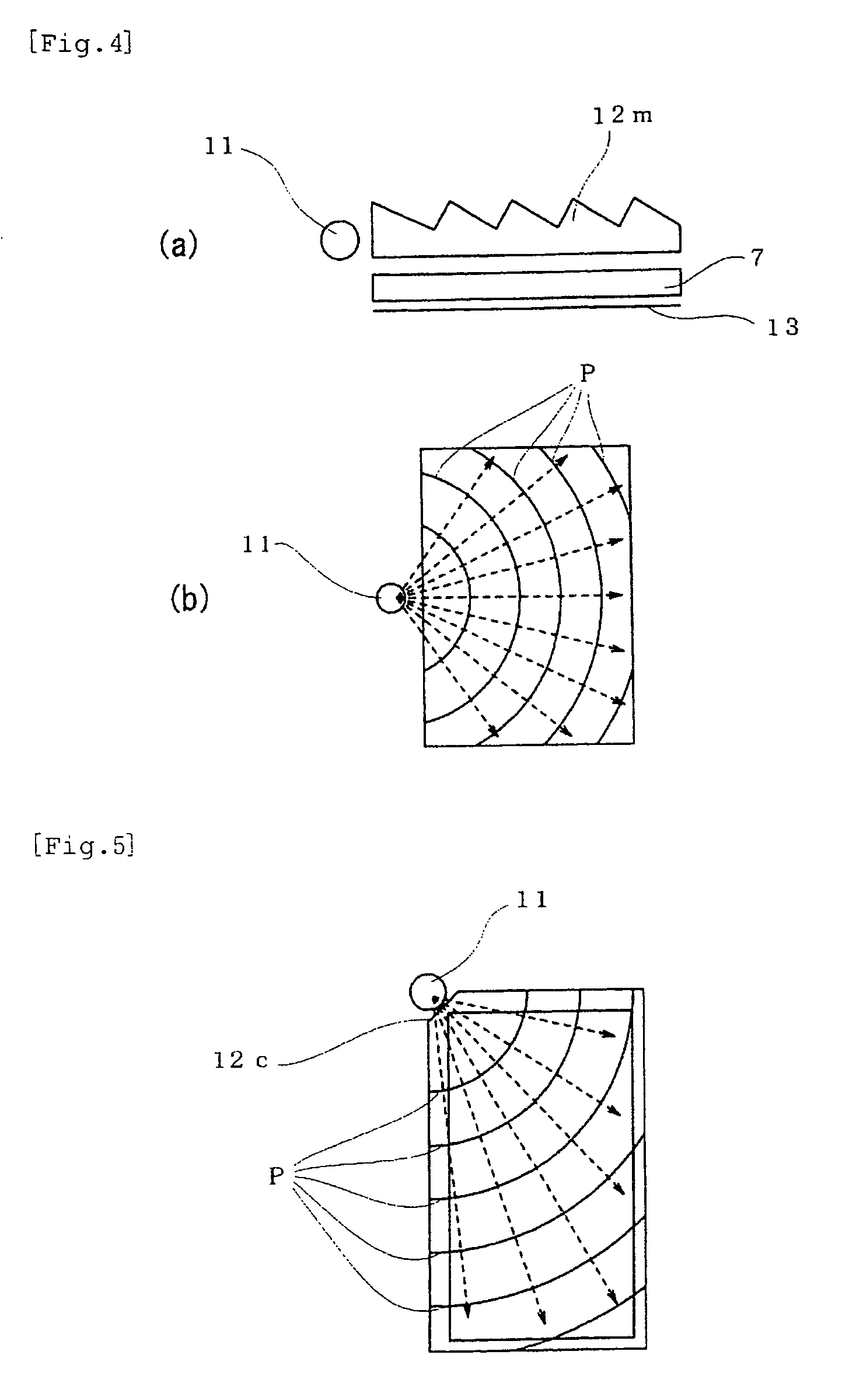
[0057] The surface light source device of the first embodiment of the invention will now be described with reference to FIG. 4(b) and FIG. 6. The surface light source device of the first embodiment, as shown in FIG. 6, comprises point light source 11, light guide 12, reflector 13, directional light-diffusing film 14, and prism sheet 15. Point light source 11 comprises a single chip-type LED, and this chip-type LED was positioned facing the central part of the end surface (end surface to which light is incident) of light guide 12, as shown in FIG. 4(b). Light guide 12 was formed of polycarbonate resin, and a plurality of concentric circular diffusion patterns centered on the light-emitting unit were formed on the lower surface of the light guide. The diffusion patterns were formed as depression 12d with a cross-section that was triangular or roughly semi-circular (half-oval) in shape, each diffusion pattern extending in a direction which intersected the direction connecting the light...

embodiment 2

[0060] A second embodiment of the invention will now be described. In the surface light device of the first embodiment, the reflector was provided separately to the light guide, but apart from the fact that an aluminum film was formed by vacuum deposition on the surface formed on the diffusion pattern of the lower surface of the light guide, the remainder of the structure was identical to that of Embodiment 1. By forming a thin metal film directly on the lower surface of the light guide, the light incident on the optical sheet can be reflected at the light-reflecting surface comprising the thin metal film and returned to the light guide, making it possible to ensure reflection of the light more reliably than the device of Embodiment 1 which reflects light using total reflection, and it is thus possible to improve the efficiency of light use.

embodiment 3

[0061] With the surface light source device of Embodiment 3, the device was made with an identical structure to that of Embodiment 1 apart from the fact that directional light-diffusing film 14 of FIG. 6 was positioned on prism sheet 15. When this surface light source device was used to illuminate a liquid crystal panel, a bright image display device with no unevenness in brightness was obtained.


PUM


Abstract

A surface light source device comprises a light emitting section (11) made of a single spot light source, a light guide plate (12), a reflective surface (13) provided on the back side of the light guide plate, and a prism pattern (15). On the light emitting surface side of the light guide plate (12), there is provided a directional light scattering film (14) consisting of at least two phases having different refractive indexes and scattering light when transmitting it. One phase of a larger refractive index includes a plenty of areas having a columnar structure extending in the thickness direction of a film and arranged to be perpendicular to a normal to the film, and exhibiting a maximum scattering angle of 10-40°.

Description

TECHNICAL FIELD [0001] The invention relates to a surface light source device, in particular a surface light source device used as a backlight in an image display device such as a liquid crystal display device or the like. BACKGROUND TECHNOLOGY [0002] Surface light source devices are conventionally used in image display devices such as liquid crystal display devices to illuminate the display panel. These surface light source devices generally comprise a light-emitting unit, a light guide, a reflector, a prism sheet and the like. A conventional surface light source device will now be described with reference to the drawings. FIG. 1 and FIG. 2 are schematic cross-sections which illustrate an example of a conventional surface light source device, and comprise light-emitting unit 1, light guide 2, reflector 3, light-diffusing film 4, and prism sheet 5. In the surface light source device of FIG. 1, the light-emitting unit comprises a light-emitting diode (LED) which is a point light sour...

Claims


Application Information

Patent Timeline
IPC IPC(8): F21V7/04F21V8/00F21Y101/02G02F1/13357G02B5/02G02B6/00
CPCG02B6/0038G02B6/0061G02B6/0051G02F1/1335
Inventor HARADA, TAKAMASAKITA, FUMIOKANAO, HIROKI
Owner TOMOEGAWA CO LTD
Why Eureka
Try Eureka