Method and arrangement for tcp flow control

a flow control and flow control technology, applied in the field of tcp flow control, can solve problems such as buffer occupancy

Inactive Publication Date: 2006-11-30
SONY CORP
View PDF16 Cites 39 Cited by
  • Summary
  • Abstract
  • Description
  • Claims
  • Application Information

AI Technical Summary

Problems solved by technology

Limiting the buffer occupancy as in this pub

Method used


Image

  • Method and arrangement for tcp flow control
  • Method and arrangement for tcp flow control
  • Method and arrangement for tcp flow control

Examples


Embodiment Construction

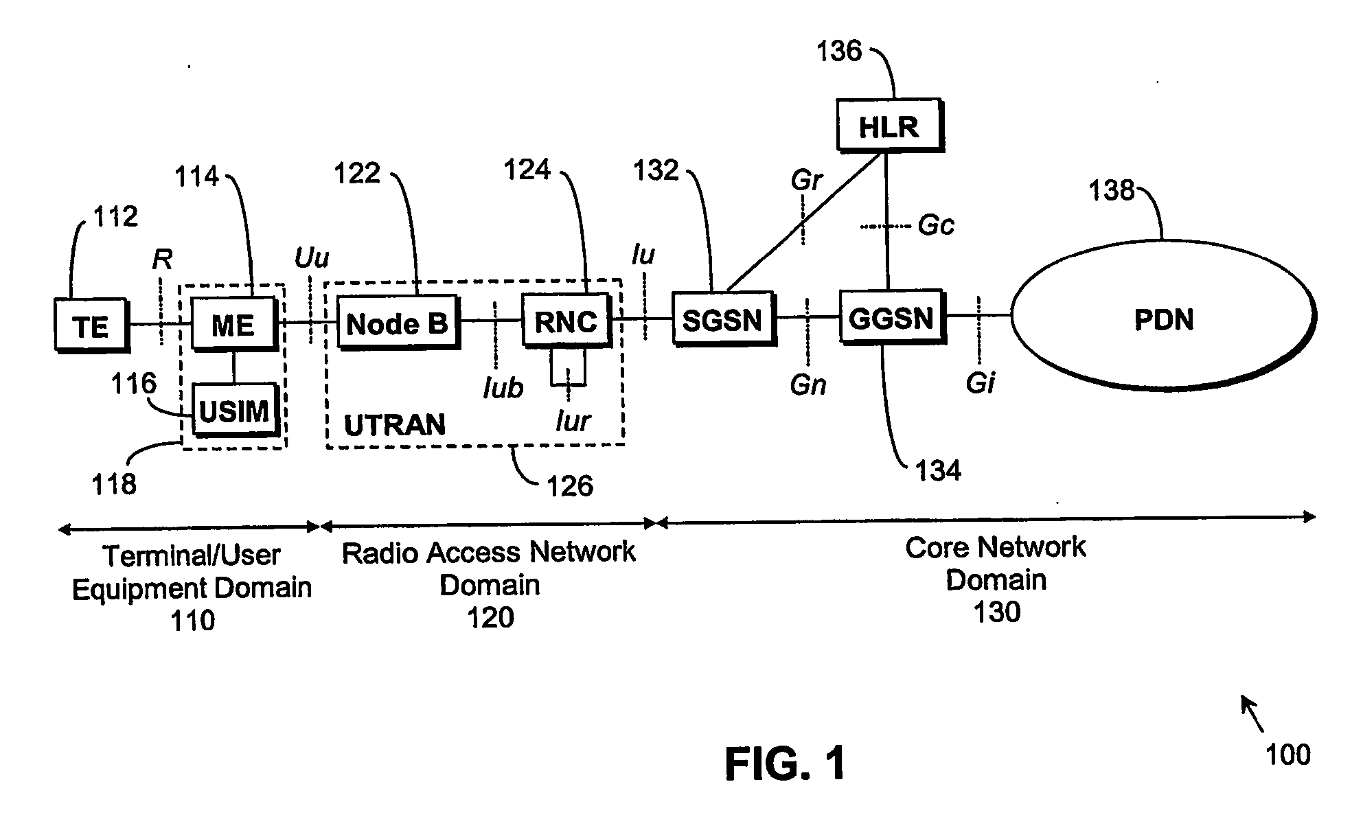
[0020] The following preferred embodiment of the present invention will be described in the context of a UMTS Radio Access Network (UTRAN) system operating in TDD mode. Referring firstly to FIG. 1, a typical, standard UMTS Radio Access Network (UTRAN) system 100 is conveniently considered as comprising: a terminal / user equipment domain 110; a UMTS Terrestrial Radio Access Network domain 120; and a Core Network domain 130.

[0021] In the terminal / user equipment domain 110, terminal equipment (TE) 112 is connected to mobile equipment (ME) 114 via the wired or wireless R interface. The ME 114 is also connected to a user service identity module (USIM) 116; the ME 114 and the USIM 116 together are considered as a user equipment (UE) 118. The UE 118 communicates data with a Node B (base station) 122 in the radio access network domain 120 via the wireless Uu interface. Within the radio access network domain 120, the Node B 122 communicates with a radio network controller (RNC) 124 via the I...


PUM


Abstract

An arrangement (124) and method (310-360) for Transmission Control Protocol (TCP) flow control in a communication system, by: determining delay in a transmit buffer of the system; and modifying TCP window size dependent on the determined delay. An indication of modified TCP window size is preferably sent to a TCP server (140) of the system in an acknowledge packet (310). The invention is particularly suitable for TCP flow control in wireless communication systems (e.g., UTRA) systems, and has the advantage that RTT (i.e., the latency of the system) can be substantially guaranteed, irrespective of the throughput that a user is allocated.

Description

FIELD OF THE INVENTION [0001] This invention relates to TCP (Transmission Control Protocol) flow control, and particularly (though not exclusively) to TCP flow control in wireless communication systems. BACKGROUND OF THE INVENTION [0002] TCP is a transport protocol in the internet protocol suite (see for example, the publication by W. R. Stevens, ‘TCP / IP illustrated, Volume 1: The protocols’, Addison-Wesley, Reading, Mass., November 1994). It is used in applications such as telnet FTP (File Transfer Protocol) and HTTP (HyperText Transfer Protocol). TCP is designed for wire networks which have very low error rates. [0003] Flow control in TCP is governed by two windows: the sender's congestion window (‘cwnd’) and the receiver's advertised window (‘awnd’). Flow control is based on the minimum of these 2 windows. The ‘cwnd’ is modified dynamically to match the capacity in the network. Most importantly it is reduced whenever packets are lost as this is an indication of congestion in the ...

Claims


Application Information

Patent Timeline
IPC IPC(8): H04J1/16H04L12/801H04L12/825H04L12/841
CPCH04L47/10H04L47/14H04L47/193H04L69/163H04L47/283H04W80/06H04L47/26H04W28/0289H04W28/10H04W8/04
Inventor SPEIGHT, TIMOTHY JAMESJELBERT, NICHOLAS
Owner SONY CORP
Why Eureka
Try Eureka