
Queue aware flow control

Active Publication Date: 2006-11-30
CISCO TECH INC
View PDF5 Cites 24 Cited by
  • Summary
  • Abstract
  • Description
  • Claims
  • Application Information

AI Technical Summary

Problems solved by technology

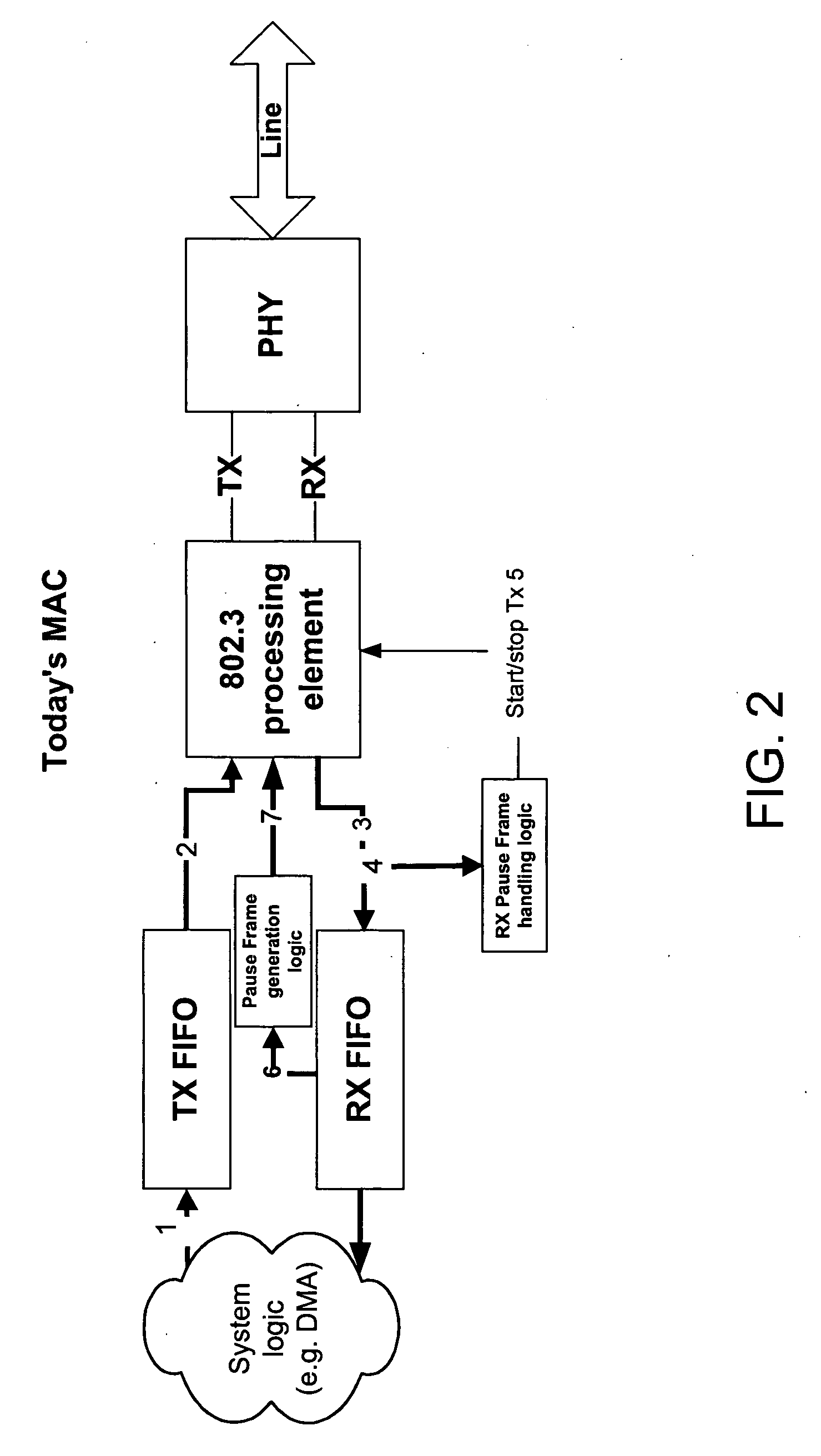
However, the current flow control using PAUSE frame does not fit very well in the backplane architecture as it does not distinguish internal queues of the system and prevents traffic to flow between unclogged queues when one of the queues become full.
The problem with PAUSE frames is that the transmitting device stops all further transmissions for duration of the PAUSE event in units of 512-bit times. This works very well for devices connected over the Ethernet network in a LAN / WAN environment.
However, this can become a Quality of Service (QoS) bottleneck in a backplane interconnect environment.

Method used


Image

  • Queue aware flow control
  • Queue aware flow control
  • Queue aware flow control

Examples


Embodiment Construction

[0016] Reference will now be made in detail to various embodiments of the invention. Examples of these embodiments are illustrated in the accompanying drawings. While the invention will be described in conjunction with these embodiments, it will be understood that it is not intended to limit the invention to any embodiment. On the contrary, it is intended to cover alternatives, modifications, and equivalents as may be included within the spirit and scope of the invention as defined by the appended claims. In the following description, numerous specific details are set forth in order to provide a thorough understanding of the various embodiments. However, the present invention may be practiced without some or all of these specific details. In other instances, well known process operations have not been described in detail in order not to unnecessarily obscure the present invention.

[0017] A first embodiment will be described in connection with a MultiGigabit SERDES backplane for Acce...


PUM


Abstract

A network flow control system utilizes flow-aware pause frames that identify a specific virtual stream to pause. Special codes may be utilized to interrupt a frame being transmitted to insert a pause frame without waiting for frame boundaries.

Description

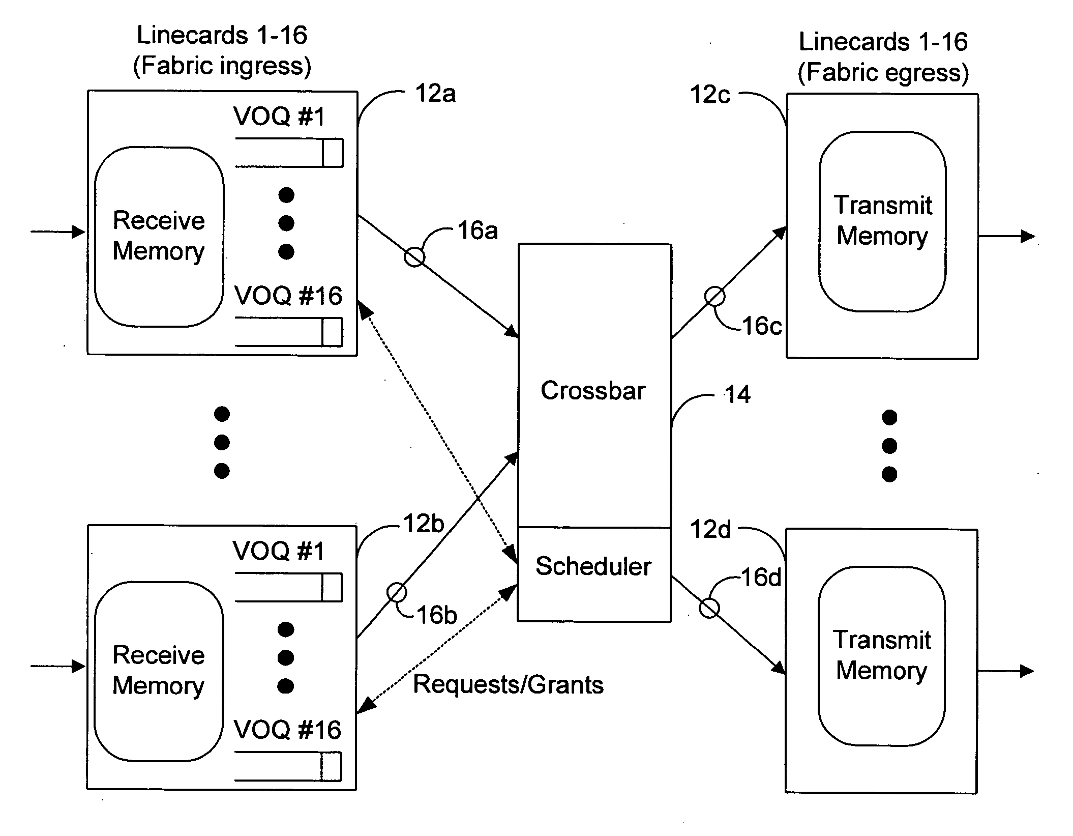
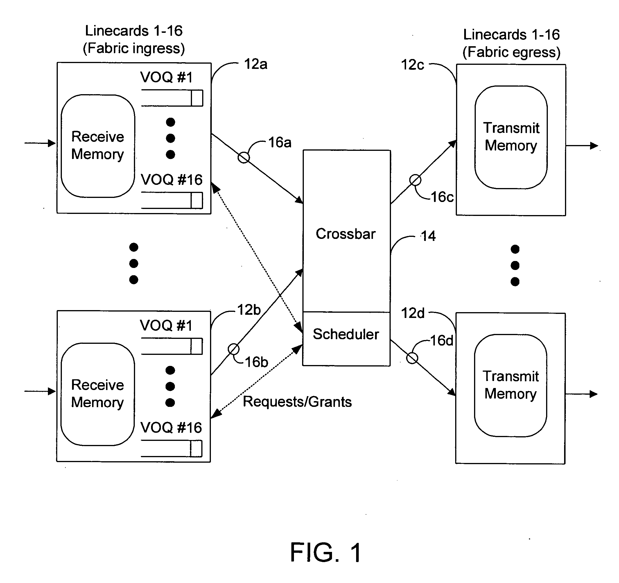
BACKGROUND OF THE INVENTION [0001] A router or switch (network device) directs packets from an input to an output. The classic network device architecture includes multiple line cards having onboard queue managers, that connect to a central switching mechanism. FIG. 1 is a high level depiction of a network device 10 depicting line cards 12 connected to a crossbar switch 14 by serial links 16. The crossbar includes crossbar switches in the form of ASICs coupled to a backplane formed of multiple serial links. The line cards act as the inputs and outputs of the router and are coupled to a backplane switching fabric which performs the task of coupling an input line card to an output line card for data transfer. Traffic from the input line card is passed through a switch the backplane switching fabric and passed to the proper output line card. High speed network device applications utilize a serial backplane where data is transferred on high-speed serial paths formed in the backplane. [0...

Claims


Application Information

Patent Timeline
IPC IPC(8): H04L12/26
CPCH04L12/5693H04L49/9078H04L47/6205H04L47/10H04L47/50
Inventor SINGLA, ANKURNAKIL, HARSHAD
Owner CISCO TECH INC
Learn More