
Fiber optic cables that are separable for optical fiber access

a fiber optic cable and optical fiber technology, applied in the field of fiber optic cables, can solve the problems of destroying the cable, destroying the cable, and preventing undesirable insect access, so as to reduce the likelihood of insect infestation and reduce the weight per length

Inactive Publication Date: 2006-11-30
CORNING OPTICAL COMM LLC
View PDF10 Cites 40 Cited by
  • Summary
  • Abstract
  • Description
  • Claims
  • Application Information

AI Technical Summary

Benefits of technology

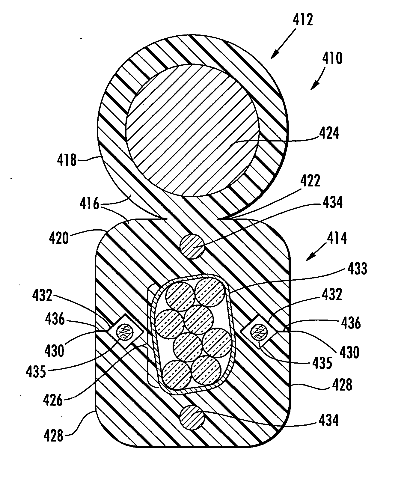
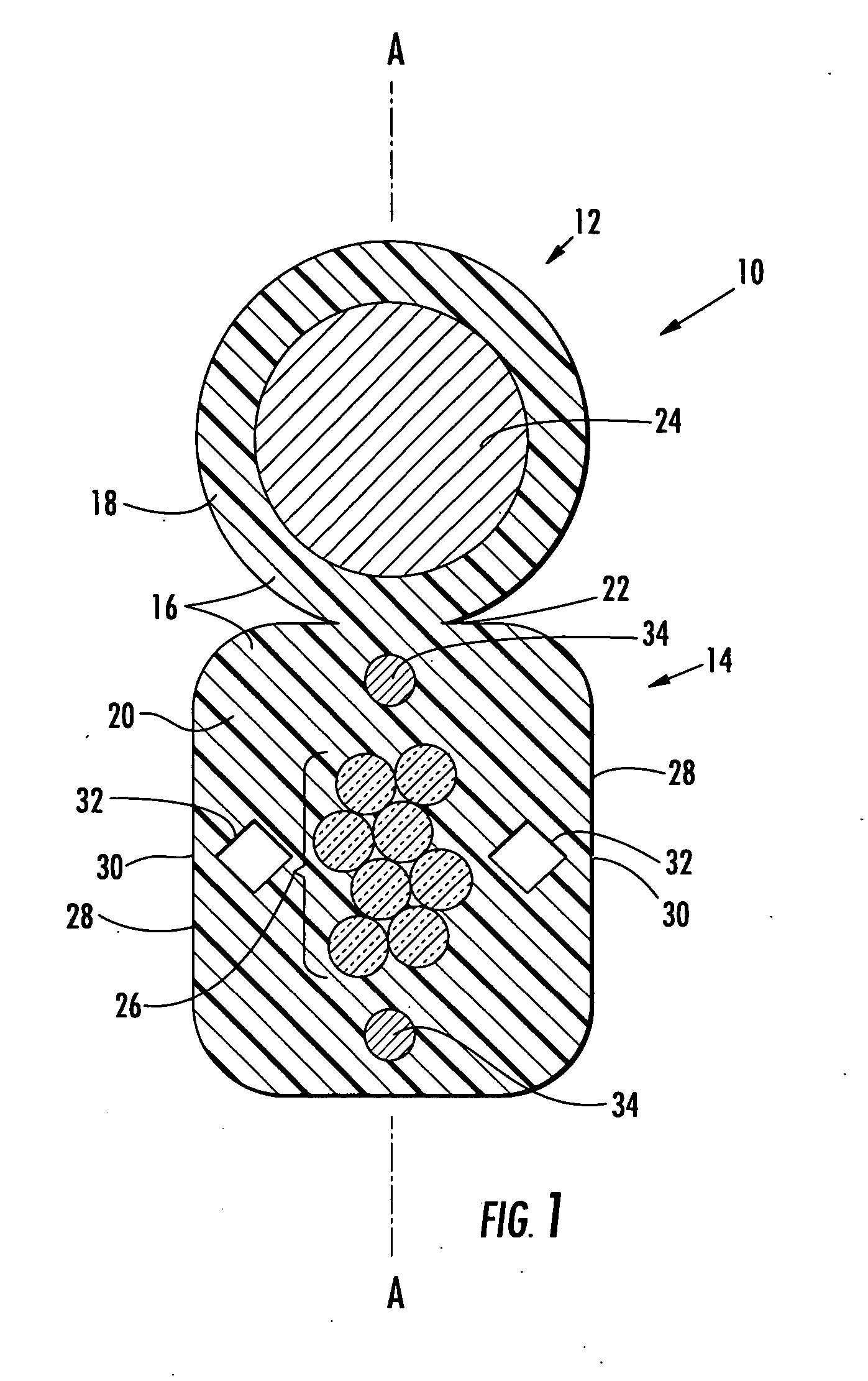
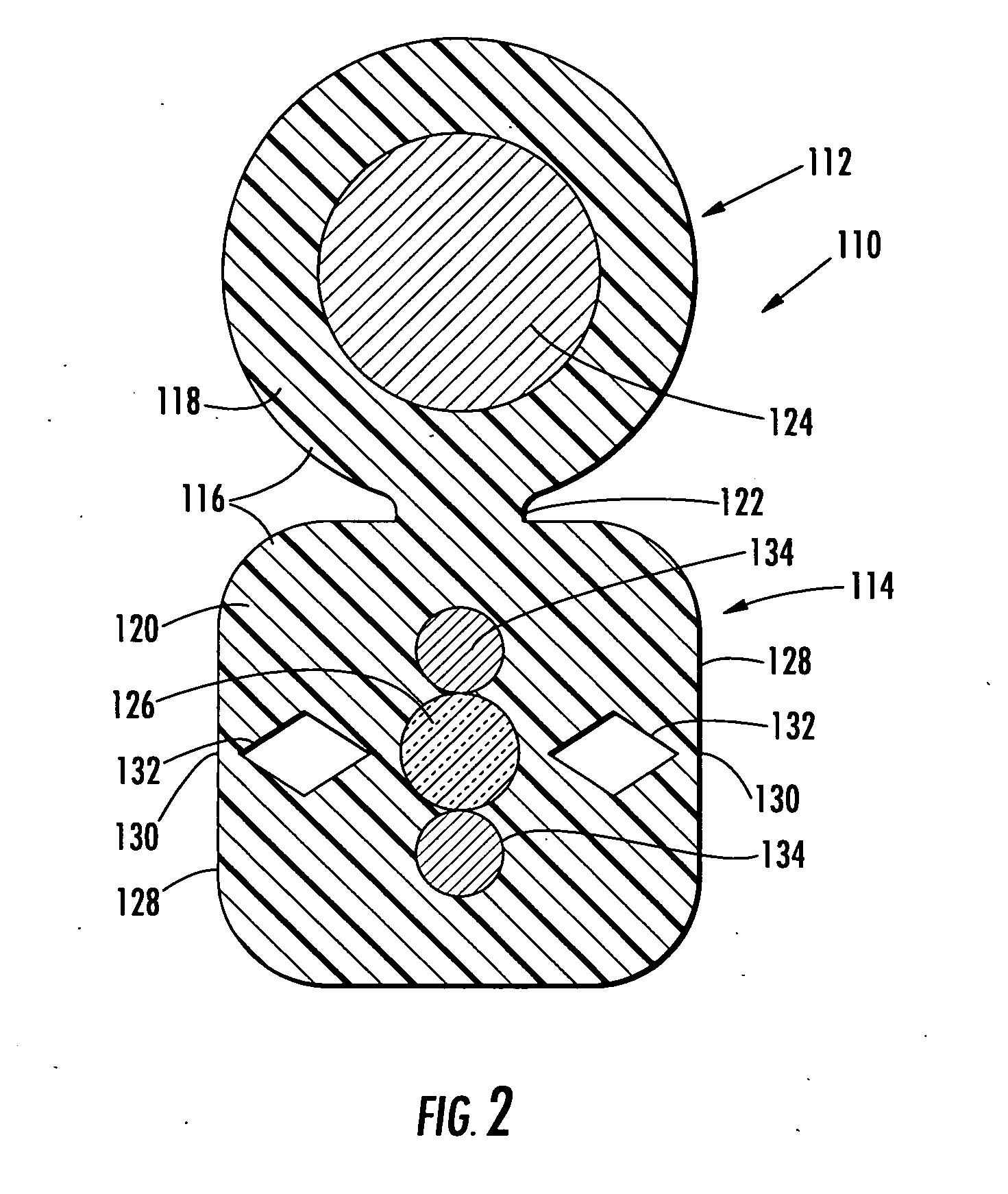
[0004] It is an objective of the present invention to provide one or more fiber optic cable designs and related methods of manufacture, whereby the fiber optic cables may include one or more of preferential tear features that allow the craft to access the optical fiber or fibers within the cable while reducing the likelihood of the laying of insect infestation. Cable designs of the present invention may have other benefits such as lower weight per length of cable, and / or other benefits as described below, or as can be learned from the following disclosure or practice of the described embodiments.
[0006] Various options and modifications are possible with each of the varieties of preferential tear portions described above. Also, if desired, the carrier jacket may also include at least one gripping area extending outwardly from a center of the carrier section in a direction away from the messenger section, thereby enhancing gripping when pulling apart the carrier section and messenger section.
[0007] According to other aspects of the invention, a separable fiber optic cable is disclosed, including a messenger section, the messenger section having at least one strength member, a carrier section, the carrier section having at least one optical fiber therein, and a common jacket. The common jacket forms a messenger jacket and a carrier jacket connected by a web. The carrierjacket defining an outer surface including at least one gripping area extending outwardly from a center of the carrier section in a direction away from the messenger section, thereby enhancing gripping when pulling apart the carrier section and messenger section. Various options and modifications are also possible for the fiber optic cables of the present invention. For example, the gripping area may include one of an extending lip or a slanted portion of the carrier jacket outer surface, if desired. Also, the concepts of the present invention may be applicable to fiber optic cables without a messenger section such as a flat drop cable.

Problems solved by technology

Unfortunately, such notches may allow the unintended consequence of insect penetration into the cable and ultimately the optical fibers, thereby damaging the cable.
Identifying and repairing such damage for a lengthy aerial drop cable can be a disruptive and expensive task.
Thus, the notches of such cable designs, while suitable for providing ready and reliable access to the optical fibers during installation or service, can be problematic in not deterring undesirable insect access after installation.

Method used


Image

  • Fiber optic cables that are separable for optical fiber access
  • Fiber optic cables that are separable for optical fiber access
  • Fiber optic cables that are separable for optical fiber access

Examples


Embodiment Construction

[0018] Detailed reference will now be made to the drawings in which examples embodying the present invention are shown. The detailed description uses numerical and letter designations to refer to features in the drawings. Like or similar designations in the drawings and description have been used to refer to like or similar parts of the invention. The drawings and detailed description provide a full and written description of the invention, and of the manner and process of making and using it, so as to enable one skilled in the pertinent art to make and use it, as well as the best mode of carrying out the invention. However, the examples set forth in the drawings and detailed description are provided by way of explanation of the invention and are not meant as limitations of the invention. The present invention thus includes any modifications and variations of the following examples as come within the scope of the appended claims and their equivalents. Examples of fiber optic cables ...


PUM


Abstract

A fiber optic cable includes a messenger section having at least one strength member, a carrier section having at least one optical fiber therein, and a common jacket that forms a common jacket. In one embodiment, the carrier jacket has a preferential tear portion adjacent to the at least one optical fiber with a substantially continuous outer surface in the carrier jacket adjacent to the preferential tear portion. The preferential tear portion may be defined by at least one of: at least one internal void, at least one weld line, and at least one wing extending from a tape disposed about the one or more optical fibers. Various alternatives are possible. For example, the carrier jacket may also or alternatively include at least one gripping area extending for enhancing the gripping of the carrier section when pulling apart the carrier section and messenger section.

Description

FIELD OF THE INVENTION [0001] The present invention relates generally to fiber optic cables. Specifically, the invention relates to fiber optic cables that are easily separable by the craft for accessing the optical fiber therein. BACKGROUND OF THE INVENTION [0002] Fiber optic cables are designed with features that provide various functions during installation and use. For example, the cables may include one or more optical fibers for transmitting signals, protection layers and jackets disposed about the optical fibers for inhibiting damage during installation or use, strength members for strengthening the cable during installation or use, and separation members or corresponding structures within the jackets to assist in separating portions of the cable or accessing the optical fibers when desired. [0003] As noted in JP Pub. No. 2002-090596, certain commonly available drop cable designs incorporate preferential tear notches or the like. The notches are located adjacent the optical f...

Claims


Application Information

Patent Timeline
IPC IPC(8): G02B6/44
CPCG02B6/4422G02B6/4495G02B6/4433G02B6/4431
Inventor BLAZER, BRADLEY J.ABERNATHY, GEORGE NEILLLOCHKOVIC, GREGORY A.ROBERTS, REGINA H.
Owner CORNING OPTICAL COMM LLC
Learn More