Portable battery powered automatic pump

a battery-powered, automatic pump technology, applied in the direction of piston pumps, positive displacement liquid engines, valve construction, etc., can solve the problems of system that is difficult to transport, power supply separation, wiring between two devices, etc., to eliminate the need for mounting brackets and facilitate assembly

Inactive Publication Date: 2006-11-30
LLEWELLYN DANIEL M
View PDF14 Cites 49 Cited by
  • Summary
  • Abstract
  • Description
  • Claims
  • Application Information

AI Technical Summary

Benefits of technology

The invention provides a single-piece device that can be easily taken aboard a small boat or other vessel without having to first remove it from its current location. This device contains a pump, a floating switch, and a battery all housed within a compact package designed to fit into the space between the deck and stern of a boat. By simply attaching a hose to the output of the pump, the device allows water to flow continuously, keeping the boat upright and avoiding potential danger of sinkage. The design uses standard components such as batteries, motors, and sensors commonly available in the industry, making assembly easier than traditional systems. Additionally, the lightweight of the battery helps ensure stability while removing the pump requires no extra hardware.

Problems solved by technology

The technical problem addressed by this patent is designing an improved boating pumping device that overcomes issues such as difficulty in transportation, high risk of damage or injury, and limited stability. Existing solutions involve separating the motor and battery which leads to complicated wiring, vulnerability to damage, and instability. Additionally, existing mounting mechanisms often require permanent attachment and significant modification of the vessel's infrastructure.

Method used


Image

  • Portable battery powered automatic pump
  • Portable battery powered automatic pump
  • Portable battery powered automatic pump

Examples


Embodiment Construction

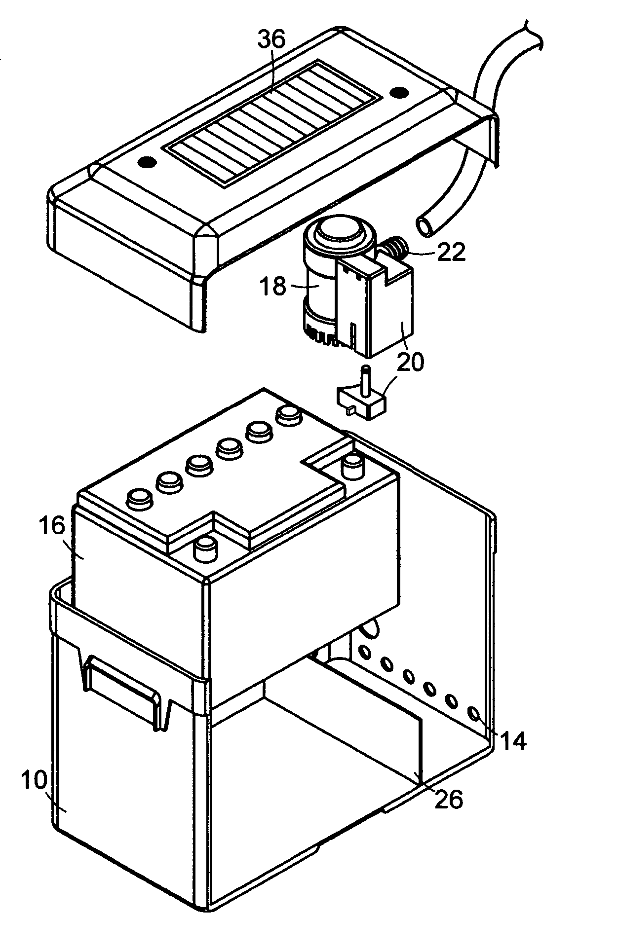
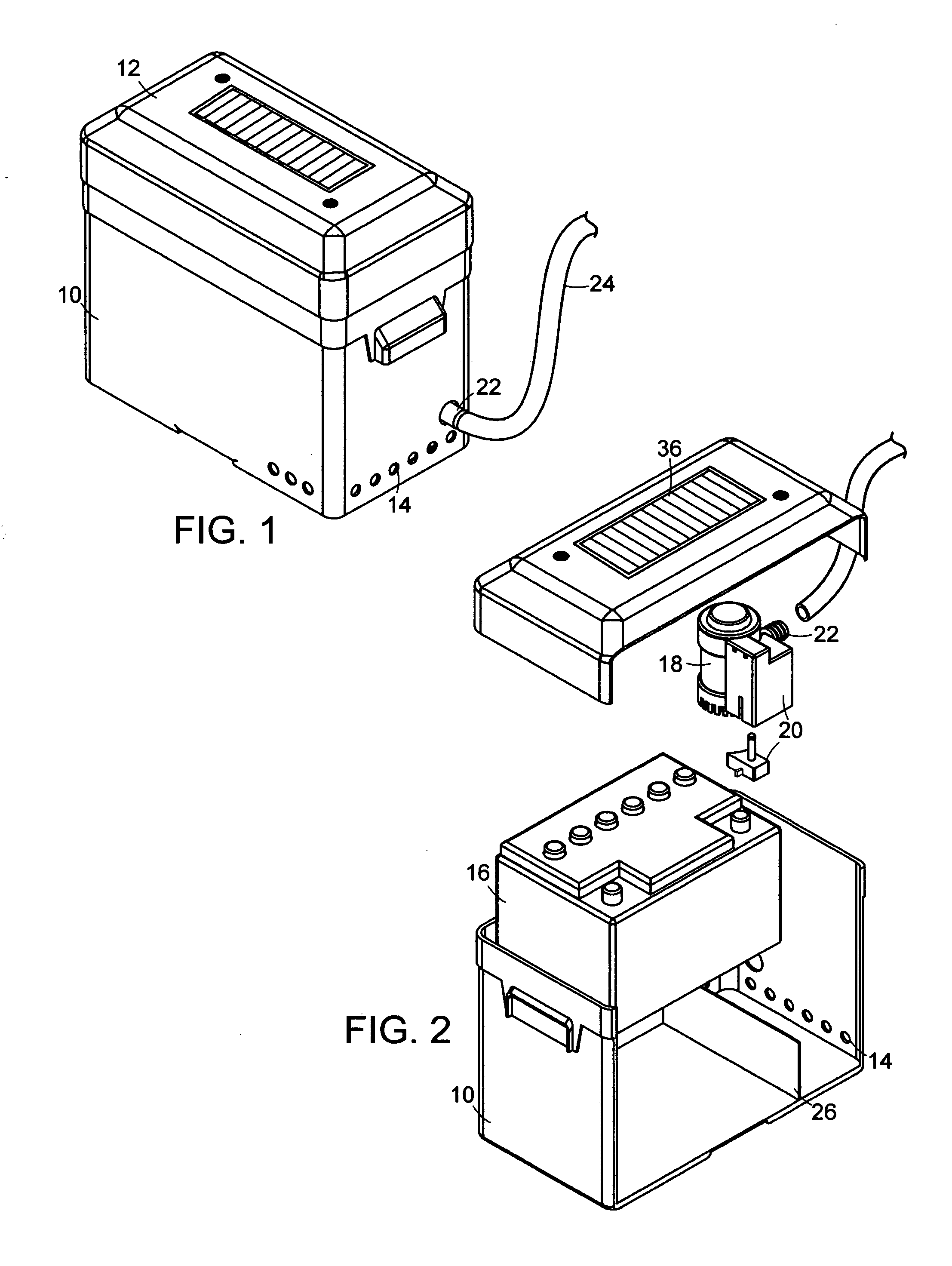
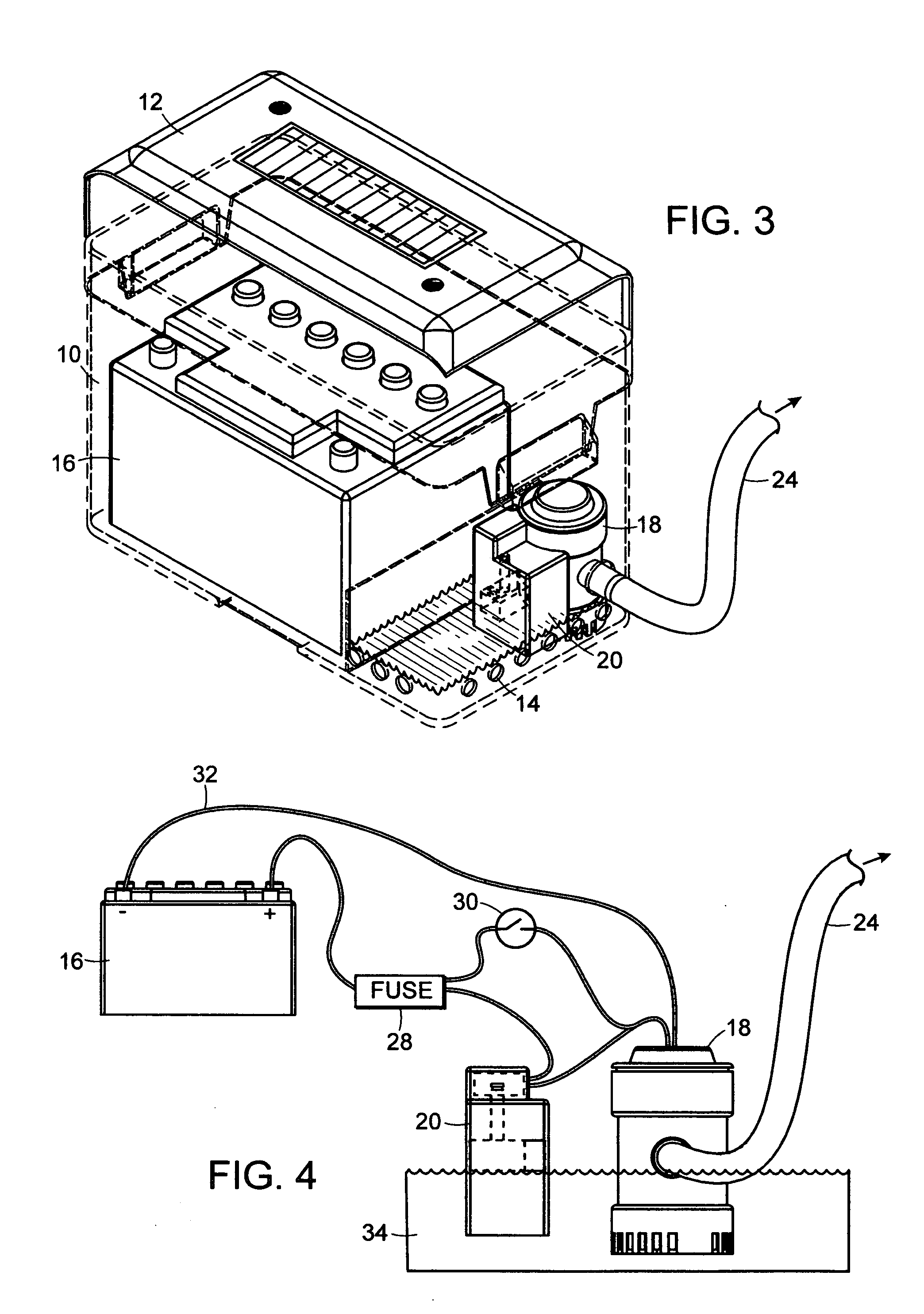
[0011] Referring now to the drawings, FIG. 1 shows the 10 box, the 12 cover, the 14 openings, the 22 pump outlet and the 24 hose. FIG. 2 shows the 18 pump, the 20 float switch, the 16 battery and the 26 divider and how they would fit into the 10 box. FIG. 3 shows the approximate position of the 18 pump and 20 switch when mounted into the 10 box as well as placement of the 16 battery. FIG. 4 is a view of the wiring schematic of the pump unit with negative voltage from the 16 battery connected directly to the battery through the 32 electrical wire and positive voltage connected to the 20 float switch through 28 fuse.

[0012] The pump unit is activated as such: When the 34 water rises to a predetermined level entering the box through 14 openings, electrical contacts inside of 20 float switch would close enabling positive voltage to flow from the 16 battery through the 20 float switch to the 18 pump. The 18 pump would turn on and begin pumping water out of 22 pump outlet and through 24 h...


PUM


Abstract

The invention is a pump system which is comprised of a box with a plurality of openings and inside of which is an electrically powered pump, a float switch and a battery. These components comprise one pumping unit. This unit is designed to rest at the bottom interior of a boat, or the bilge area, for the purpose of pumping water out of the boat automatically when the water reaches a predetermined level in the boat. The pump unit is portable and self contained with no additional power source or wiring needed.

Description


Claims


Application Information

Patent Timeline
Owner LLEWELLYN DANIEL M
Why Eureka
Try Eureka