Connector

a technology of connecting rods and connectors, applied in the direction of coupling device connection, engagement/disengagement of coupling parts, electrical apparatus, etc., can solve the problems of affecting the operation of the connector assembly, the size of the housing and the entire connector assembly must be larger, and the above-described moving plate tends to shake, so as to reduce the shaking of the moving plate and minimize the shaking

Active Publication Date: 2006-11-30
SUMITOMO WIRING SYST LTD
View PDF7 Cites 22 Cited by
  • Summary
  • Abstract
  • Description
  • Claims
  • Application Information

AI Technical Summary

Benefits of technology

[0009] The rib that projects from the rear surface of the hood slidably engages the insertion hole in the moving plate as the moving plate moves rearward in the hood along the fit-in direction. The sliding engagement of the rib in the insertion hole prevents the moving plate from tilting. Connectors that rely only on the peripheral wall of the moving plate to prevent the moving plate from tilting in the hood have a large distance between the tilt-preventing structures if the connector is large. However, the present invention also has the rib and the insertion hole. Therefore, the span between the portions that prevent tilting is short, and shaking of the moving plate is minimized or avoided. Furthermore the rib and the insertion hole are provided in a dead space. Therefore, the housings and the connector are not enlarged.
[0010] A guide wall preferably is formed on a periphery ...

Problems solved by technology

However, the above-described moving plate tends to shake longitudinally in such in a narrow male housing.
However, an increase in the size of the peripheral wall of the moving plate requires a correspondi...

Method used


Image

  • Connector
  • Connector
  • Connector

Examples


Embodiment Construction

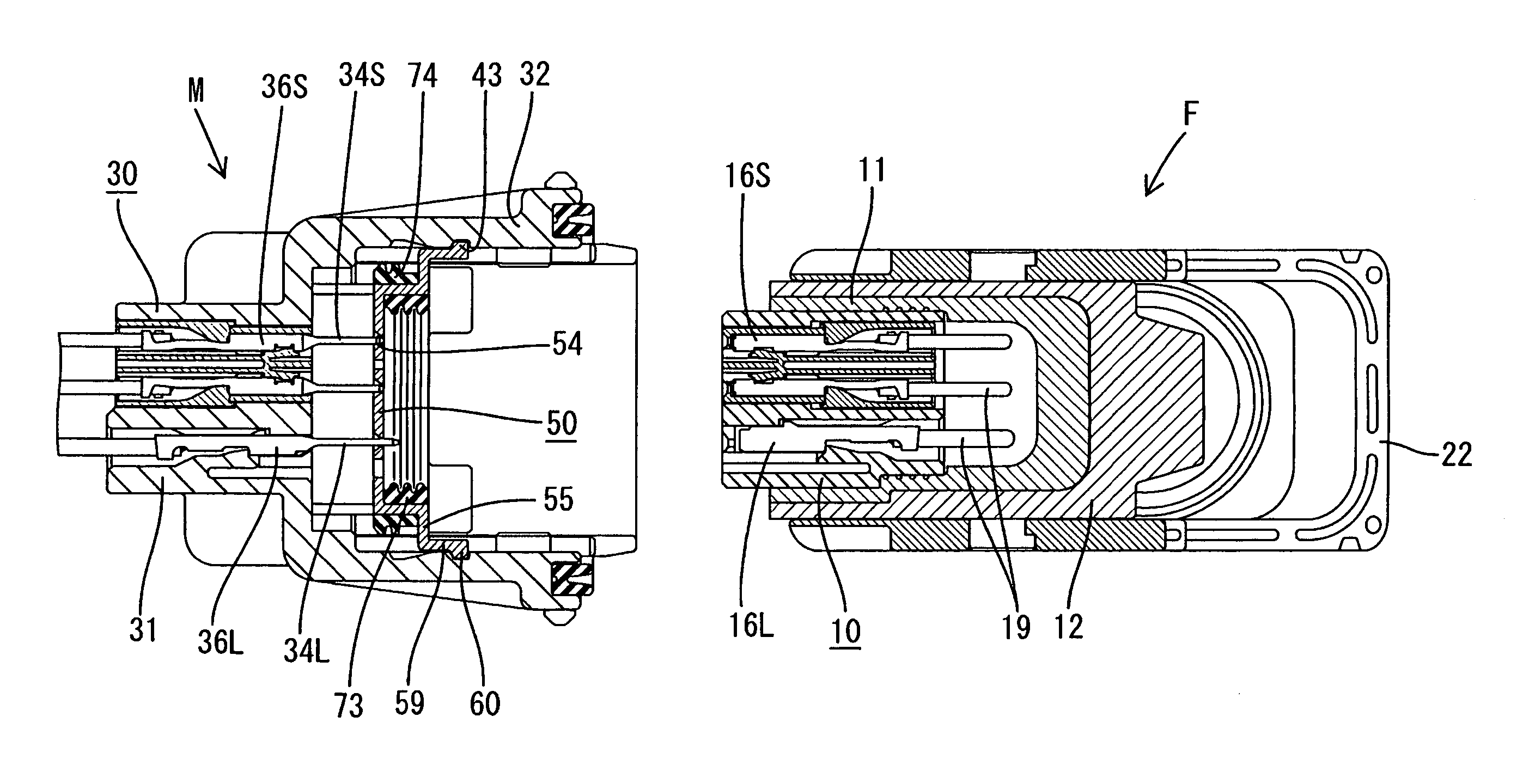
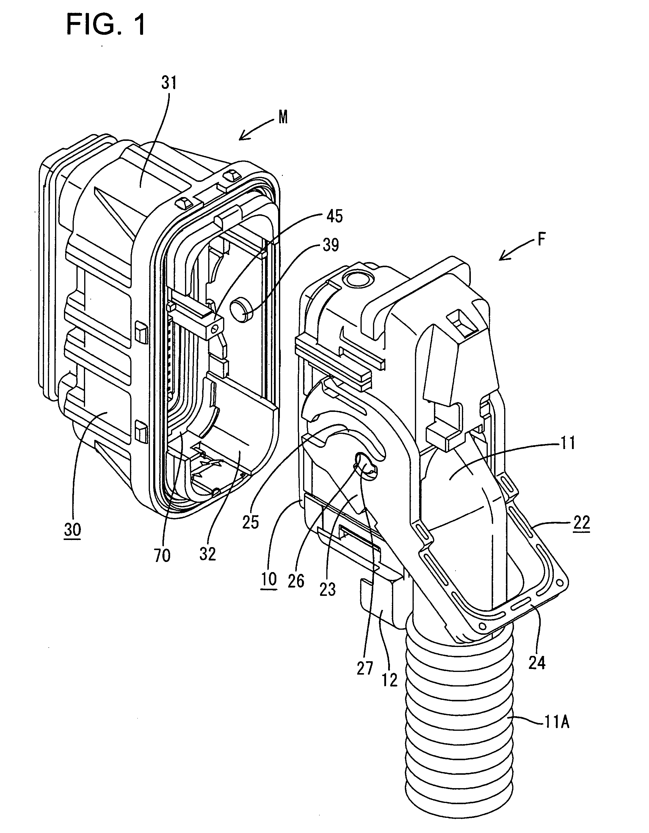
[0027] A connector assembly in accordance with the invention includes a male connector and a female connector identified respectively by the letters M and F in FIGS. 1 through 14. As explained herein, the female connector is configured to fit in the male connector M. Mating ends of the male and female connectors M and F are referred to herein as the front.

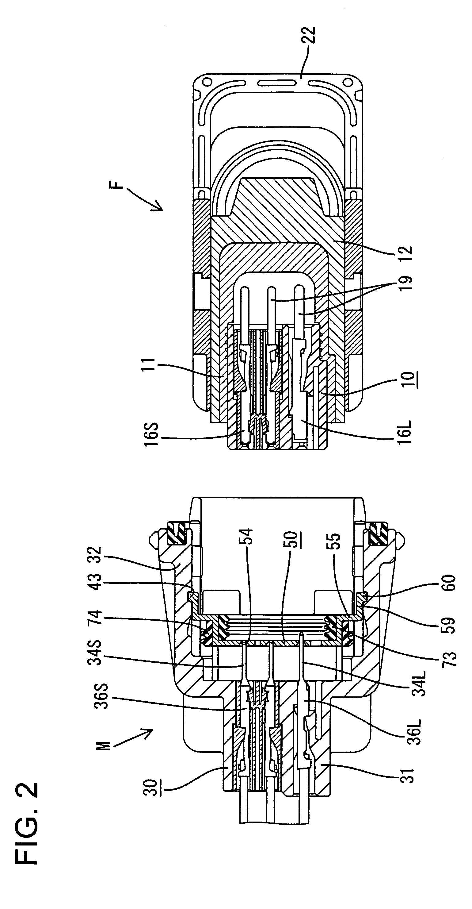
[0028] As best shown in FIG. 2, the female connector F has a vertically long and narrow female housing 10, made of synthetic resin. A rubber grommet 11 is mounted on a peripheral surface of the female housing 10 to cover a rear portion of the female housing 10. A grommet cover 12 made of synthetic resin is mounted on the peripheral surface of the grommet 11, and a lever 22 is mounted on a peripheral surface of the grommet cover 12, for fitting the female connector F in the male connector M.

[0029] As shown in FIG. 4, large cavities 15L are arranged longitudinally in a row in a right-hand region of the female housing 10, as viewed ...


PUM


Abstract

A male housing (30) has a hood (32) and a rib (45) that projects forward in the hood (32). A moving plate (50) is disposed movably in the hood (32) and an insertion hole (62) is formed on a body (51) of the moving plate (50) for receiving the rib (45). Guide walls (64, 65) are formed on the periphery of the insertion hole (62). The moving plate (50) is pressed into the hood (32) from an initial position by a female housing (10). Peripheral sides of the moving plate (50) are guided by the hood (32) and peripheral surfaces of the rib (45) slide in contact with the guide walls (64, 65) to prevent the moving plate (50) from shaking.

Description

BACKGROUND OF THE INVENTION [0001] 1. Field of the Invention [0002] The present invention relates to a connector having a moving plate. [0003] 2. Description of the Related Art [0004] U.S. Pat. No. 4,797,116 shows a connector assembly that has a male housing with a forwardly open hood and a female housing that can fit into the hood along a fit-in direction. Male terminal fittings are mounted in the male housing and have tabs that project into the hood. A moving plate is mounted in the hood for movement along the fit-in direction. The moving plate has holding holes that receive the tabs to maintain a correct alignment of the tabs and to prevent the tabs from being deformed by an external force. The moving plate is mounted in the hood so that the distal ends of the tabs are in the holding holes. The mating female housing can be fit in the hood of the male housing so that the opposed female and male terminal fittings connect to each other. The moving plate moves to the rear end of the ...

Claims


Application Information

Patent Timeline
IPC IPC(8): H01R13/44
CPCH01R13/62938H01R13/645H01R13/631H01R13/6295H01R13/4538
Inventor ISHIKAWA, YOSHIYUKIOKURA, YOSHIO
Owner SUMITOMO WIRING SYST LTD
Why Eureka
Try Eureka