Article of footwear incorporating a fluid system

a technology of fluid system and filter system, which is applied in the field of filter system, can solve the problems other components, and detracting from so as to achieve the effect of adversely affecting the aesthetic properties of footwear and the mechanical properties of the bladder

Inactive Publication Date: 2006-12-07
NIKE INC
View PDF36 Cites 50 Cited by
  • Summary
  • Abstract
  • Description
  • Claims
  • Application Information

AI Technical Summary

Benefits of technology

[0011] In one embodiment, the filter is located on the outer surface of the footwear and a bladder is located in the sole structure. As the wearer walks or runs, air passes through the filter and the bladder is inflated. The purpose of the filter is to prevent liquids and particulates from entering the system, thereby adversely affecting the aesthetic properties of the footwear and the mechanical properties of the bladder and other components. For example, dust and water may collect in portions of the bladder that are visible, thereby detracting from the aesthetic properties of the footwear. Furthermore, deposits of liquids and particulates may prevent components of the invention from functioning properly.
[0012] A variety of materials may be used for the filter, including polytetrafluoroethylene, expanded polytetrafluoroethylene, high density polyethylene, ultrahigh molecular weight polyethylene, polyvinylidene fluoride, polypropylene, and ceramic filter materials. In order to assist in preventing water and other liquids from entering the system, the filter may be both hydrophobic and oleophobic. A perforated layer of material may be placed over exterior portions of the filter to protect and support the filter.

Problems solved by technology

The purpose of the filter is to prevent liquids and particulates from entering the system, thereby adversely affecting the aesthetic properties of the footwear and the mechanical properties of the bladder and other components.
For example, dust and water may collect in portions of the bladder that are visible, thereby detracting from the aesthetic properties of the footwear.

Method used


Image

  • Article of footwear incorporating a fluid system
  • Article of footwear incorporating a fluid system
  • Article of footwear incorporating a fluid system

Examples


first embodiment

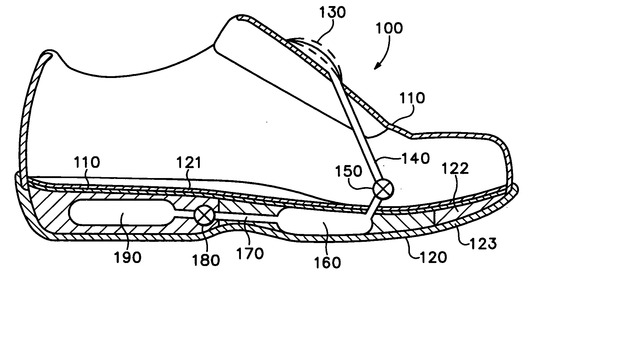
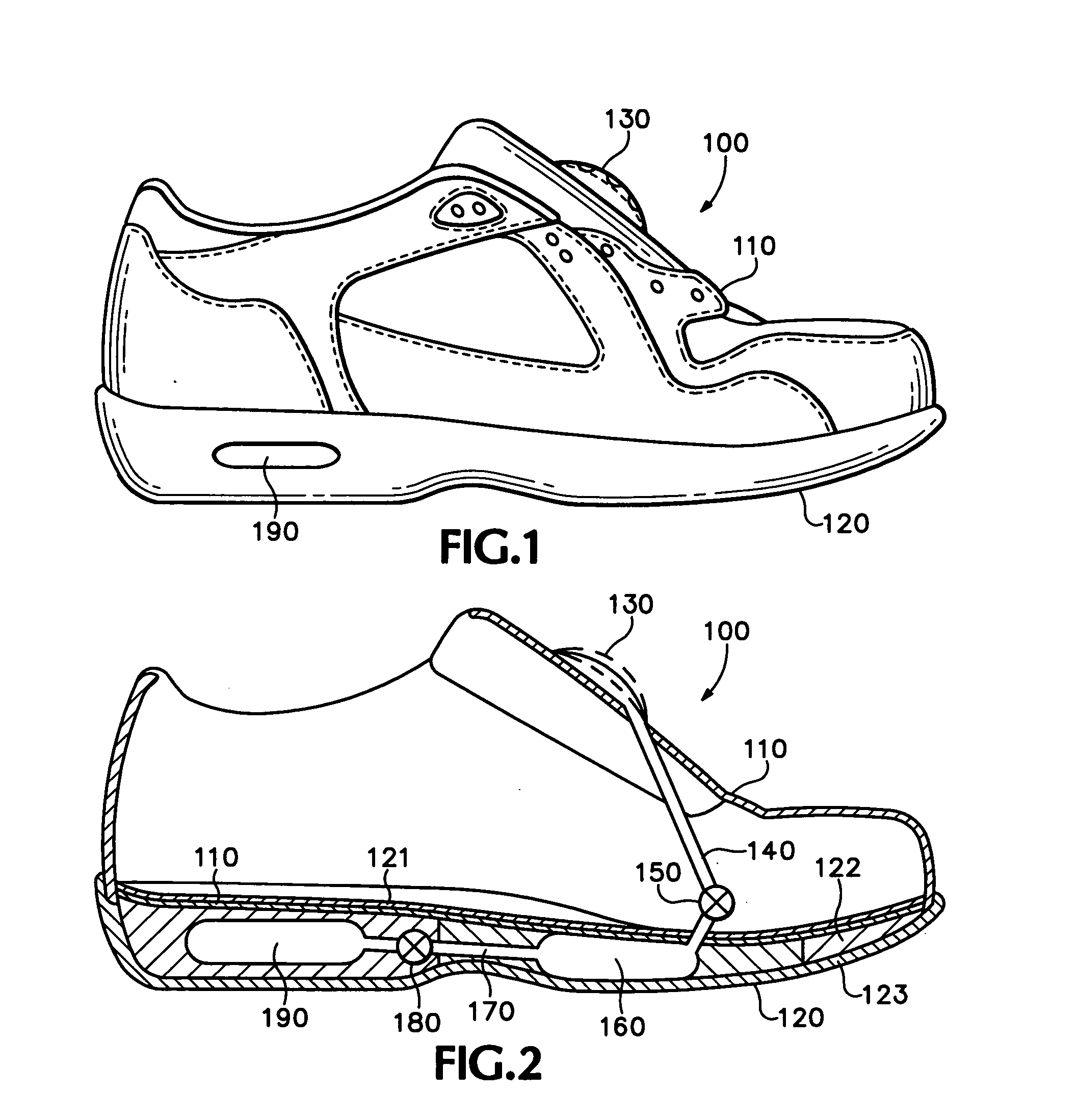
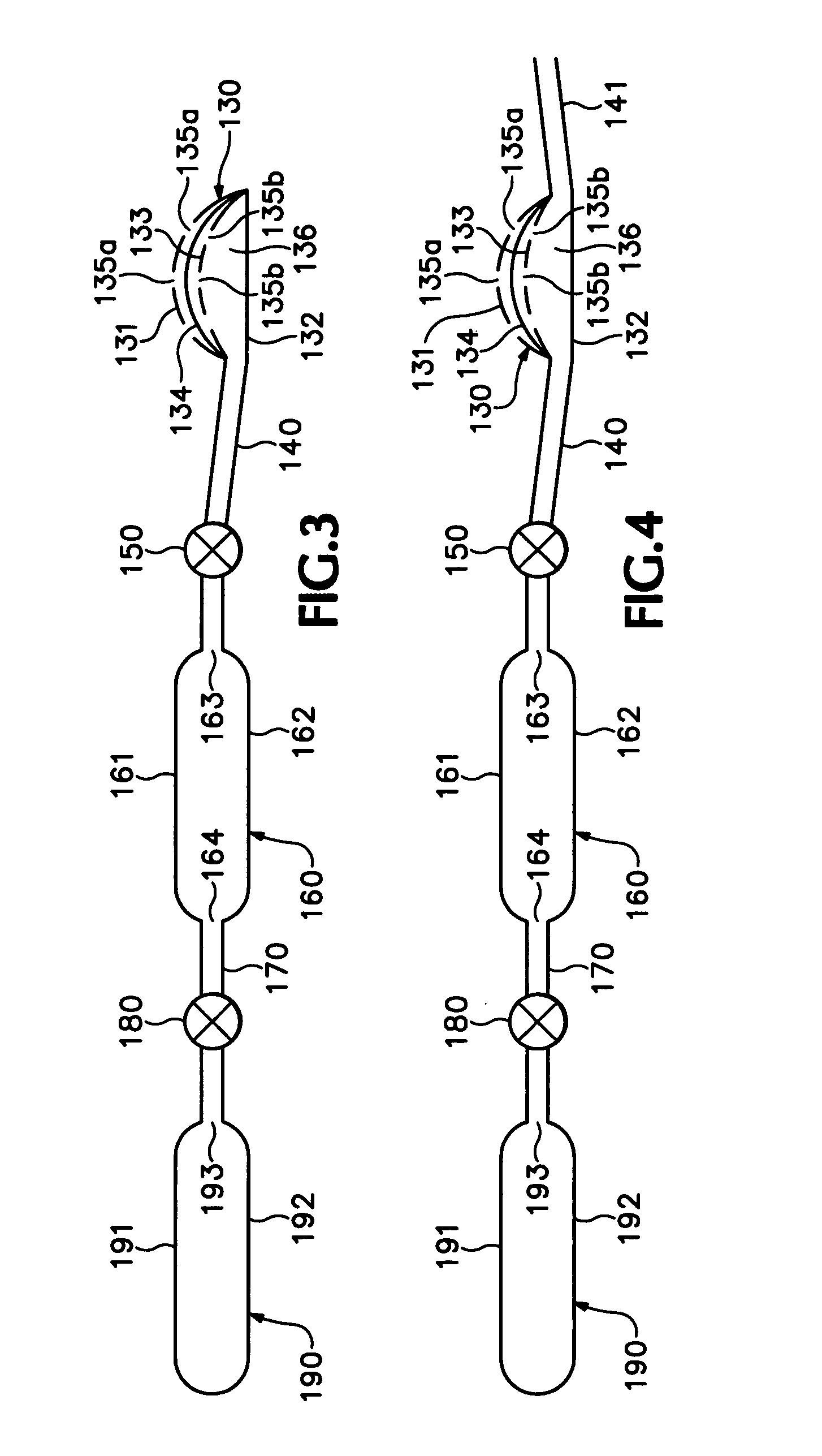
[0027] With regard to the first embodiment, depicted in FIGS. 2 and 3, footwear 100 also includes a filter structure 130 that permits air to enter a first conduit 140 but restricts the entry of liquids and particulates. Conduit 140, which may include a first valve 150, places filter structure 130 in fluid communication with a pump 160. A second conduit 170, which may include a second valve 180, places pump 160 in fluid communication with a bladder 190. Accordingly, air may pass through filter structure 130 and, through the action of the various components, enter bladder 190.

[0028] The purpose of the various components of the first embodiment are to inflate bladder 190 with air, thereby providing midsole 122 with enhanced shock-absorbing properties. When worn by an individual, during running for example, footwear 100 repetitively contacts the playing surface and, following each contact, disengages from the playing surface. When in contact with the playing surface pump 160 is compress...

second embodiment

[0052]FIG. 6, which discloses the present invention, depicts a cross-section of an article of footwear 100a having an upper 110a, a sole structure 120a, and a filter 134a. A pump 160a is located in the forefoot portion of footwear 100a and a bladder 190a is located in the heel portion of a midsole 122a. A conduit 170a having a valve 180a permits air to flow from pump 160a to bladder 190a. Filter 134a is attached to the upper surface of pump 160a such that air from within upper 110a may pass through filter 134a and enter pump 160a.

[0053] The purpose of this embodiment is to disclose an alternate means of inflating a bladder, in this case bladder 190a, to a pressure that is greater than atmospheric pressure. When footwear 100a is not in contact with the playing surface, midsole 122a and pump 160a are fully expanded. In this state, pump 160a becomes filled with air which is at approximately atmospheric pressure. When footwear 100a contacts the playing surface, the foot of the wearer c...

third embodiment

[0054] The third embodiment, depicted in FIG. 7, includes a filter material that is used in conjunction with a ventilation system. Footwear 200 includes an upper 210 and a sole structure 220. The ventilation system, which may be primarily located in sole structure 220, includes a filter 230 that permits air to flow into a first conduit 240. First conduit 240 includes a first valve 250 that permits air to flow into a bladder 260 but not in the reverse direction. A second conduit 270 leads from bladder 260 to a second valve 280. Beyond second valve 280, second conduit 270 branches into a plurality of ventilation conduits 290 that lead to the interior of upper 210. A plurality of filters 230′ cover the ends of ventilation conduits 290 to prevent liquids and particulates from entering the system. In the alternative, a single section of filter 230′ may be positioned so as to cover all of the ends of ventilation conduits 290. The compression of bladder 260 forces air into ventilation cond...


PUM


Abstract

An article of athletic footwear having an air-filled bladder disposed in a sole structure is disclosed. The air-filled bladder is in fluid communication with ambient air through a filter that permits ambient air to enter the bladder but restricts liquids and particulates from entering the bladder. In operation, the filter and bladder may be portions of a bladder system that absorb shock when the footwear contacts a playing surface. Alternatively, the filter and bladder may be portions of a bladder system that ventilates the interior of the footwear. The filter may be formed of a material such as expanded polytetrafluoroethylene that is attached to a carrier.

Description

CROSS-REFERENCE To RELATED APPLICATION [0001] This non-provisional U.S. patent application is a continuation application of U.S. patent application Ser. No. 11 / 053,697, which was filed in the U.S. Patent and Trademark Office on Feb. 7, 2005 and entitled Footwear With Bladder Filter. U.S. patent application Ser. No. 11 / 053,697 is a continuation application of U.S. patent application Ser. No. 09 / 887,523, which is now abandoned and was filed in the U.S. Patent and Trademark Office on Jun. 21, 2001 and entitled Footwear With Bladder Filter. Each prior U.S. patent application is entirely incorporated herein by reference.BACKGROUND OF THE INVENTION [0002] 1. Field of the Invention [0003] The present invention relates to footwear. More particularly, the present invention relates to a filter system that prevents water, other liquids, and particulates from obstructing the operation of components located within an article of footwear. [0004] 2. Description of Background Art [0005] The princip...

Claims


Application Information

Patent Timeline
Patent Type & Authority Applications(United States)
IPC IPC(8): A43B7/06A43B7/08A43B7/12A43B13/20
CPCA43B7/081A43B13/206A43B13/203A43B7/125
Inventor PASSKE, JOEL L.DOJAN, FREDHAZENBERG, PETER K.SWIGART, JOHN
Owner NIKE INC
Why Eureka
Try Eureka