Lattice boom crane for lifting heavy loads

a boom crane and crane technology, applied in the direction of cranes, portable lifting, hoisting equipment, etc., can solve the problems of reducing load, affecting the economics of the crane, and potentially not being able to lift the heavy ultimate load with such a crane, and achieve the effect of quick connection

Active Publication Date: 2006-12-07
TADANO DEMAG GMBH
View PDF4 Cites 11 Cited by
  • Summary
  • Abstract
  • Description
  • Claims
  • Application Information

AI Technical Summary

Benefits of technology

[0014] One of several basic concepts underlying the present invention is to couple at least two individual lattice boom cranes, which are actually designed for the lifting of less heavy loads, for the lifting of very heavy loads in the above-described manner. Because at least two individual cranes are releasably coupled to one unit according to the invention, only minor modifications to the individual lattice boom cranes are necessary in order to now be able to increase the loading capacity of an individual lattice boom crane so as to lift exceedingly heavy loads. At the same time, it is also possible to continue to use the individual lattice boom cranes for their originally intended purpose. This modular concept requires no disproportionately high reconstruction and also further allows the economical use of the individual lattice boom cranes in the use domains originally intended for them. In particular, it is possible with fewer additional parts and thus costs to combine the load capacities of the individual lattice boom cranes, so that even greater loads can be lifted than the sum of the individual loads of the individual cranes.
[0020] Still another exemplary embodiment of the present invention envisions that the two lower chassis are rigidly connected to each other and at least one crawler is disposed on each outer-lying side of the two lower chassis. The crane is thus very capable of rotating about a point. Proceeding to the side or in the longitudinal direction is only possible in a severely limited manner, but can be made easier by lifting a pair of opposing crawlers from the ground.
[0021] The main function of each connection consists in that the position of the individual cranes with respect to each other is secured. This can also take place by a connection element that connects the upper chassis with each other. This would have the advantage that the rotary joint of the individual cranes can be further used in order to orient the crawlers either in the longitudinal or traverse directions and / or in intermediate positions. The connection of the connecting elements with the upper chassis can be made, e.g., by means of bolt or screw-fastening. In addition, a quick connection can be advantageously used, such as the one described in DE 19549244C2.

Problems solved by technology

The lifting of heavy ultimate loads is then potentially not possible with such a crane.
For lesser loads, such a crane is not economical, because the purchase and operation costs are higher than the costs of a smaller crane.
However, the necessary safety is ensured only under specifically defined conditions with such so-called tandem or multiple-lifts, as a rule, due to the problematic load distribution or the fact that the crane is equipped with individual controllers.
The problem with this arrangement is that the position of the two cranes is not fixed relative to each other and thus it results in constraining forces, whereby the load must be reduced.
It cannot be operated economically with only one boom.
Moreover, a ring lift crane is, as a rule, not portable and is consequently severely limited in its work area, because this is possible only with a relatively high technical effort.

Method used


Image

  • Lattice boom crane for lifting heavy loads
  • Lattice boom crane for lifting heavy loads
  • Lattice boom crane for lifting heavy loads

Examples


Embodiment Construction

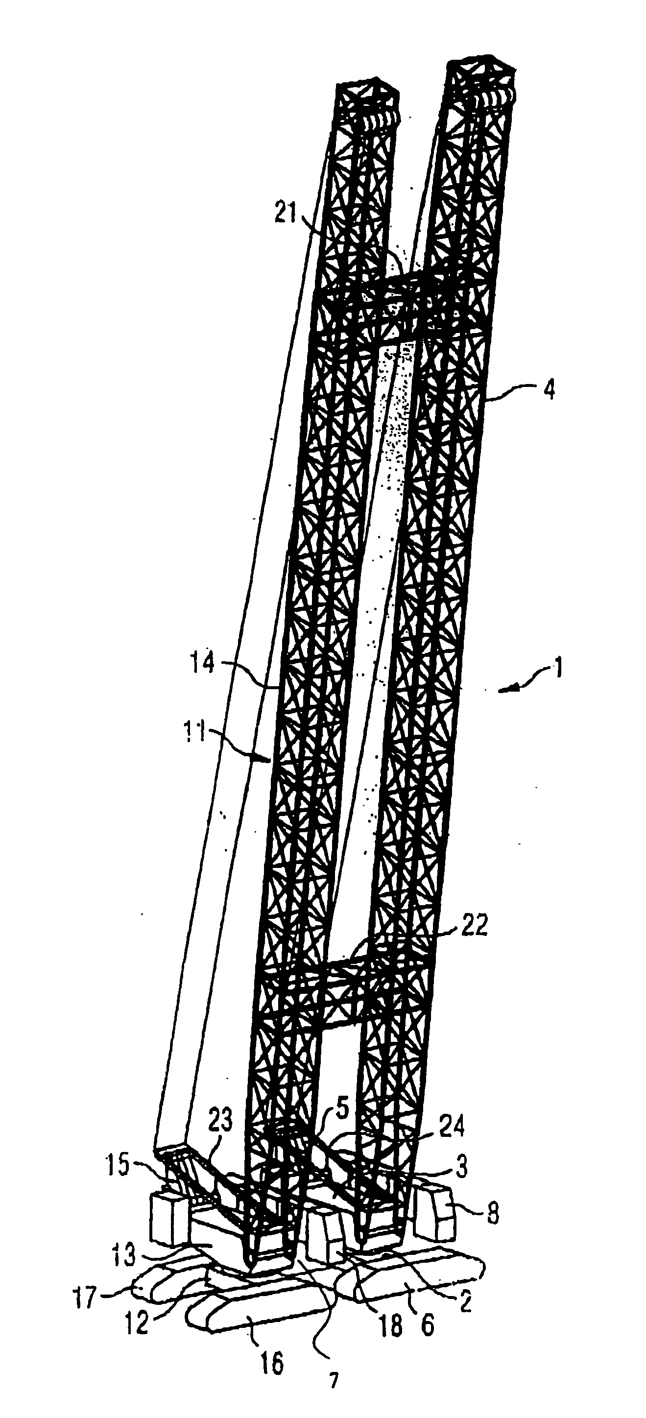
[0035] In FIG. 1, a first exemplary embodiment of an inventive lattice boom crane with a crawler mechanism is shown in perspective illustration. In this exemplary embodiment, the inventive lattice boom crane comprises two individual lattice boom cranes 1, 11, each of which comprises a lower chassis 2, 12 and an upper chassis rotatably disposed thereon. A lattice boom 4, 14 is tiltably affixed on each respective upper chassis 3, 13. The tilting angle of the two lattice booms 4, 14 is adjustable by a tilting mechanism 5, 15, respectively, which are only schematically illustrated herein. The tilting mechanisms 5, 15 comprise not shown tilting winches, on each of which a cable is wound; the cables are respectively affixed to each scaffold trestle 23, 24. By winding and unwinding of the two cables, each respective tilt angle is adjustable. Due to the fact that the tilting mechanisms 5, 15 are synchronized according to the present invention, which synchronization can take place in an elec...


PUM


Abstract

The invention concerns a lattice boom crane, which is composed of at least two individual lattice boom cranes (1, 11), which each comprise a luffing lattice boom (4, 14), whose luffing angle is adjustable by a luffing mechanism (5, 15). The lattice booms (4, 14) of the individual lattice boom cranes (1, 11) are connected with each other and oriented in parallel and adjacent to each other and the luffing mechanisms (5, 15) of the lattice boom cranes (1, 11) are synchronously operated, such that the rigidly-connected lattice booms (4, 14) are synchronously luffable.

Description

CROSS REFERENCE TO RELATED APPLICATIONS [0001] This patent application claims priority of German Patent Application Serial No. 10 2005 021 859.8-22 filed May 11, 2005, which application is incorporated herein by reference. FIELD OF THE INVENTION [0002] The present invention concerns a lattice boom crane for lifting heavy loads, such as, e.g., reactors, generators, distillation columns or the like. BACKGROUND OF THE INVENTION [0003] Cranes are always designed for a specific ultimate load range. The lifting of heavy ultimate loads is then potentially not possible with such a crane. For lesser loads, such a crane is not economical, because the purchase and operation costs are higher than the costs of a smaller crane. Nevertheless, in order to lift increased loads without having to purchase a larger crane, it is already known to lift a load with multiple cranes simultaneously. However, the necessary safety is ensured only under specifically defined conditions with such so-called tandem ...

Claims


Application Information

Patent Timeline
Patent Type & Authority Applications(United States)
IPC IPC(8): B66C23/06
CPCB66C23/64B66C23/36
Inventor ZOLLONDZ, RUEDIGERWECKBECKER, ALFONSNOESKE, INGOKARP, GUENTER
Owner TADANO DEMAG GMBH
Why Eureka
Try Eureka