
Systems and methods for image reconstruction of sensitivity encoded MRI data

Active Publication Date: 2006-12-07
THE UNIV OF UTAH
View PDF15 Cites 55 Cited by
  • Summary
  • Abstract
  • Description
  • Claims
  • Application Information

AI Technical Summary

Benefits of technology

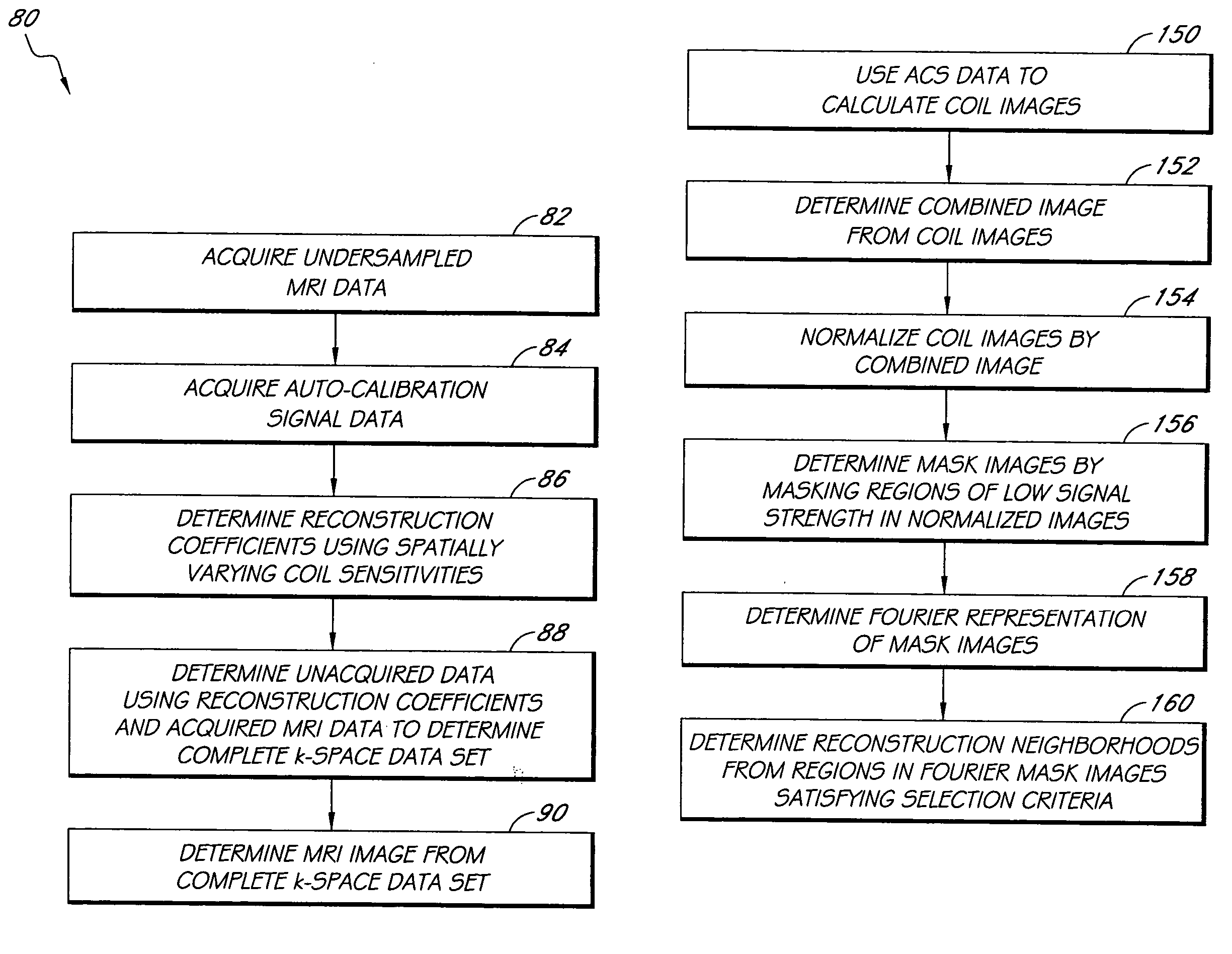
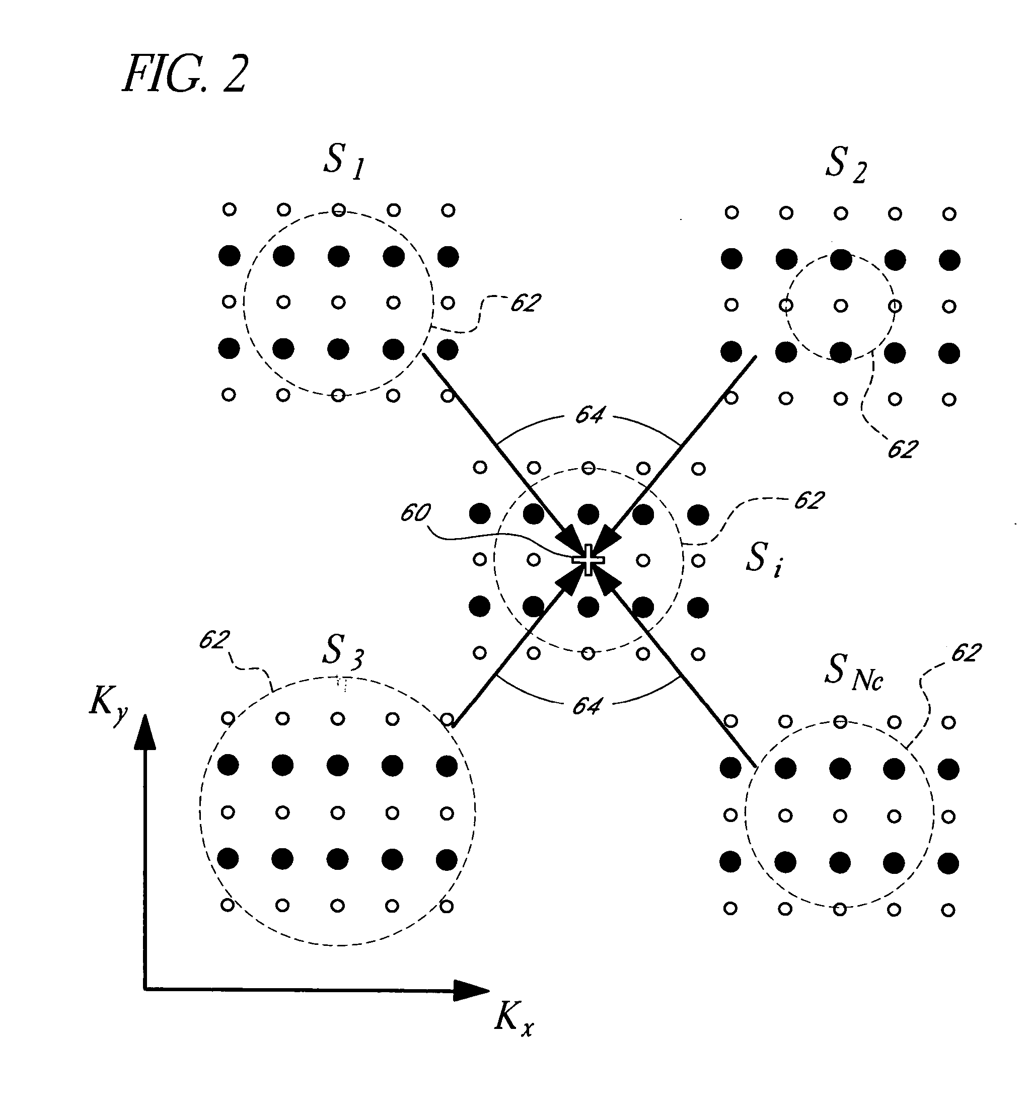
[0012] An embodiment of a system for reconstructing sensitivity-encoded magnetic resonance (MRI) data from a target is presented herein. The system comprises two or more receiver coils configured to be disposed near the target. The coils are configured to receive from the target acquired MRI data, with the data being representable in an acquired portion of the frequency domain. The frequency domain comprises a first and a second frequency dimension. The system further comprises a sampling module configured to communicate with at least one of the two or more receiver coils so as to receive the acquired MRI data from each of the receiver coils and output undersampled MRI data;. The system also comprises an image reconstruction processor configured to identify an unacquired portion of the frequency domain in which the undersampled MRI data has not been acquired. The unacquired portion and the acquired portion may be combined to provide a fully sampled portion of the frequency domain. The image reconstruction processor

Problems solved by technology

However, sampling at the Nyquist rate is time consuming and can prevent imaging targets that move (e.g., a beating heart).
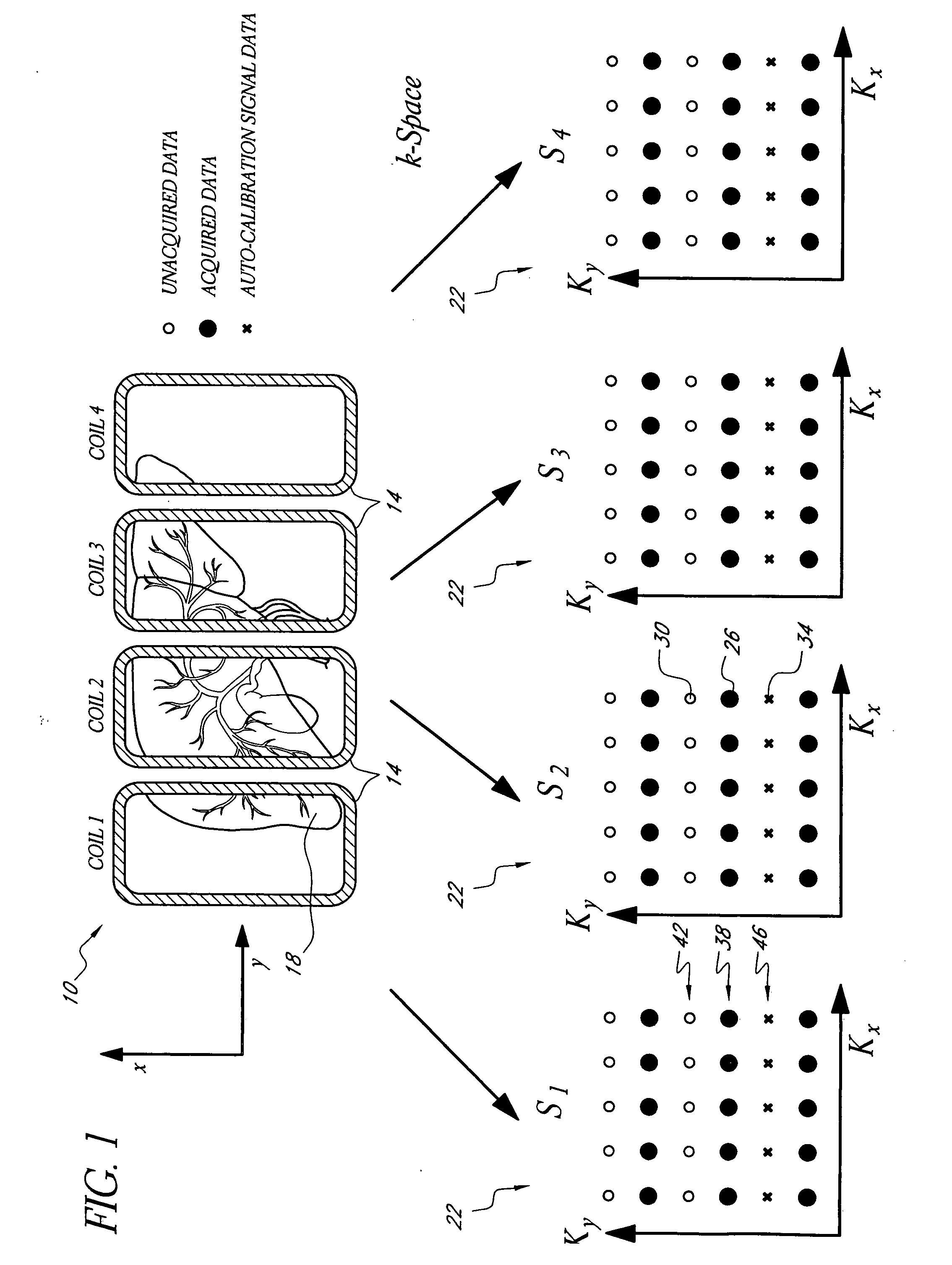
The undersampling results in certain data in k-space not being acquired, and therefore not available for image reconstruction.
Although, some P-MRI methods have produced good-quality images from MRI data acquired at lower reduction factors, many of the present P-MRI methods suffer from strong noise amplification and non-resolved aliasing artifacts when the MRI data is acquired at higher reduction factors.
Moreover, certain P-MRI methods require time-consuming calibration scans that can provide erroneous data due to, for example, target motion between the calibration scan and the imaging scan.

Method used


Image

  • Systems and methods for image reconstruction of sensitivity encoded MRI data
  • Systems and methods for image reconstruction of sensitivity encoded MRI data
  • Systems and methods for image reconstruction of sensitivity encoded MRI data

Examples


Embodiment Construction

[0023] For convenience and ease of presentation only, the following detailed description is generally directed to systems and methods for two-dimensional (“2-D”) [e.g., (xy)] image reconstruction from 2-D Cartesian k-space [e.g., (kx,ky) ] MRI data. However, this is not a limitation on the systems and methods disclosed herein, and certain embodiments of the invention are directed toward 3-D [e.g., (x,y,z)] image reconstruction from 3-D Cartesian k-space [e.g., (kx,ky,kz)] MRI data. The systems and methods disclosed herein can also be applied to parallel or partially parallel MRI systems with undersampling in more than one phase encoding direction (e.g., ky,kz). Accordingly, it is understood that the systems and methods disclosed herein are general in nature and are not limited to the 2-D Cartesian embodiments shown and described for illustrative and / or example purposes.

[0024]FIG. 1 schematically illustrates acquisition of frequency domain MRI data in a parallel MRI system 10 having...


PUM


Abstract

Methods and systems in a parallel magnetic resonance imaging (MRI) system utilize sensitivity-encoded MRI data acquired from multiple receiver coils together with spatially dependent receiver coil sensitivities to generate MRI images. The acquired MRI data forms a reduced MRI data set that is undersampled in at least a phase-encoding direction in a frequency domain. The acquired MRI data and auto-calibration signal data are used to determine reconstruction coefficients for each receiver coil using a weighted or a robust least squares method. The reconstruction coefficients vary spatially with respect to at least the spatial coordinate that is orthogonal to the undersampled, phase-encoding direction(s) (e.g., a frequency encoding direction). Values for unacquired MRI data are determined by linearly combining the reconstruction coefficients with the acquired MRI data within neighborhoods in the frequency domain that depend on imaging geometry, coil sensitivity characteristics, and the undersampling factor of the acquired MRI data. An MRI image is determined from the reconstructed unacquired data and the acquired MRI data.

Description

CROSS-REFERENCE TO RELATED APPLICATIONS [0001] This application claims the benefit under 35 U.S.C. §119(e) of U.S. Provisional Patent Application No. 60 / 675,002, titled GENERALIZED AUTOCALIBRATING RECONSTRUCTION FOR SENSITIVITY ENCODED MRI, filed on Apr. 25, 2005, and U.S. Provisional Patent Application No. 60 / 773,373, titled GENERALIZED AUTO-CALIBRATING TECHNIQUE FOR IMAGE RECONSTRUCTION FROM SENSITIVITY ENCODED MRI DATA, filed on Feb. 14, 2006. Each of the aforementioned provisional patent applications is hereby incorporated by reference herein in its entirety.STATEMENT REGARDING FEDERALLY SPONSORED R&D [0002] This invention was made with government support under Contract Numbers R01HL53596, R01EB177-02, R01HL57990, and R01HL48223 awarded by the National Institutes of Health. The government has certain rights to this invention.BACKGROUND [0003] 1. Field of the Invention [0004] The present disclosure relates to magnetic resonance imaging (MRI) methods, and more particularly to MRI ...

Claims


Application Information

Patent Timeline
IPC IPC(8): G01V3/00
CPCG01R33/5611
Inventor KHOLMOVSKI, EVGUENI G.PARKER, DENNIS LEE
Owner THE UNIV OF UTAH
Learn More