Digital camera comprising smear removal function

a digital camera and function technology, applied in the field of digital cameras comprising smear removal functions, can solve the problems of image quality deterioration, signal-noise ratio deterioration, image quality deterioration

Inactive Publication Date: 2006-12-07
CASIO COMPUTER CO LTD
View PDF6 Cites 37 Cited by
  • Summary
  • Abstract
  • Description
  • Claims
  • Application Information

AI Technical Summary

Benefits of technology

[0010] In accordance with an aspect of the present invention, there is provided an imaging apparatus comprising an image pickup device having a horizontal optical black region and a vertical optical black region; a storage control means for storing pixel signals in the vertical optical black region among pixel signals outputted from the image pickup device in a storage means; a first calculation means for calculating a value of pixel signals in the horizontal optical black region based on pixel signals of one or more pixels in the horizontal optical black region among the pixel signals outputted from the image pickup device; a second calculation means for calculating a value of pixel signals in the vertical optical black region based on pixel signals of one or more pixels in the vertical optical black region among the pixel signals outputted from the image pickup device; a subtraction means for subtracting the pixel signal stored in the storage means from the pixel signal outputted from the image pickup device; and a subtraction control means for controlling the degree of subtraction by the subtraction means based on the difference between the value calculated by the first calculation means and the value calculated by the second calculation means.
[0011] In accordance with another aspect of the present invention, there is provided an imaging apparatus comprising an image pickup device having a vertical optical black region 1 and a vertical optical black region 2; a storage control-means for storing pixel signals in the vertical optical black region among pixel signals outputted from the image pickup device in a storage means; a calculation means for calculating a value of the difference between a pixel signal of a pixel in the vertical optical black region 1 and a pixel signal of a pixel in the vertical optical black region 1 for every column among the pixel-signals outputted from the image pickup device; a subtraction means for subtracting the pixel signal stored in the storage means from the pixel signal outputted from the image pickup device; and a subtraction control means for controlling whether or not subtraction by the subtraction means is performed based on the value calculated by the calculation means for every column.

Problems solved by technology

For the past number of years, in image pickup devices such as a CCD, there has been a problem that a white line called smear is generated in the imaged image data due to entrance of intense light (for example, sunlight, car headlight and the like), leading to deteriorated image quality.
However, in this case, there has been a problem that since the pixel signals of the pixels in the vertical optical black region are subtracted uniformly, deterioration of the signal-noise ratio or deterioration of image quality is caused in the case that smear is not generated intensely.
Further, in the case that smear is generated diagonally due to movement of the camera or an object, there has been a problem that deterioration of image quality is also caused when the pixel signals of the pixels in the vertical optical black region are uniformly subtracted.

Method used


Image

  • Digital camera comprising smear removal function
  • Digital camera comprising smear removal function
  • Digital camera comprising smear removal function

Examples


first embodiment

A. First Embodiment

[0026] A-1. Structure of the Digital Camera

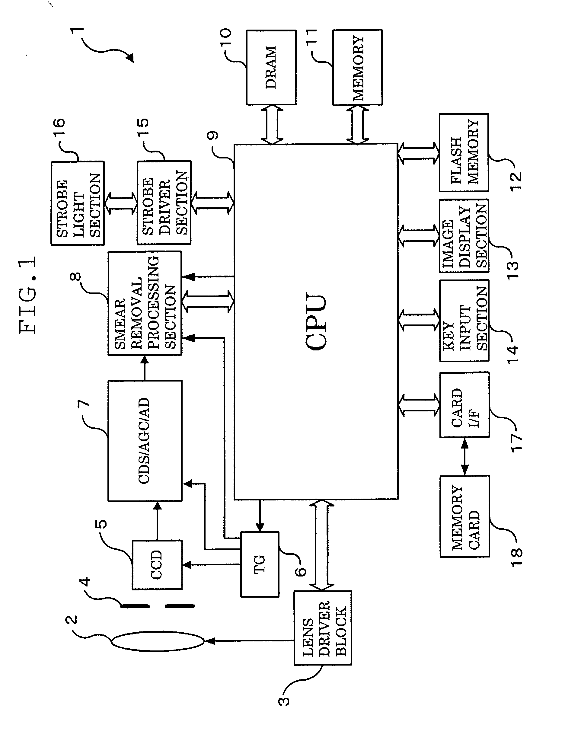
[0027]FIG. 1 is a block diagram showing an electrical outline structure of a digital cameral 1 which realizes the imaging apparatus of the present invention.

[0028] The digital camera 1 comprises an image pickup lens 2, a lens driver block 3, an aperture / shutter combination 4, a CCD 5, a timing generator (TG) 6, a unit circuit 7, a smear removal processing section 8, a CPU 9, a DRAM 10, a memory 11, a flash memory 12, an image display section 13, a key input section 14, a strobe driver section 15, a strobe light section 16, and a card I / F 17. A memory card 18 removably inserted in an unshown card slot of the digital camera 1 main body is connected to the card I / F 17.

[0029] The image pickup lens 2 includes an unshown focus lens and an unshown zoom lens, and is connected to the lens driver block 3. The lens driver block 3 is composed of unshown motors for driving the focus lens and the zoom lens in the optical axis direct...

second embodiment

B. Second Embodiment

[0128] Next, descriptions will be hereinafter given of a second embodiment.

[0129] In the second embodiment, though the digital camera 1 having the structure similar to the structure shown in FIG. 1 is used, the structure of the smear removal processing section 8 is slightly different.

[0130] B-1. Smear Removal Processing Section 8

[0131] Here, descriptions will be given of the outline of the present invention in the second embodiment before description of the smear removal processing section 8 in the second embodiment.

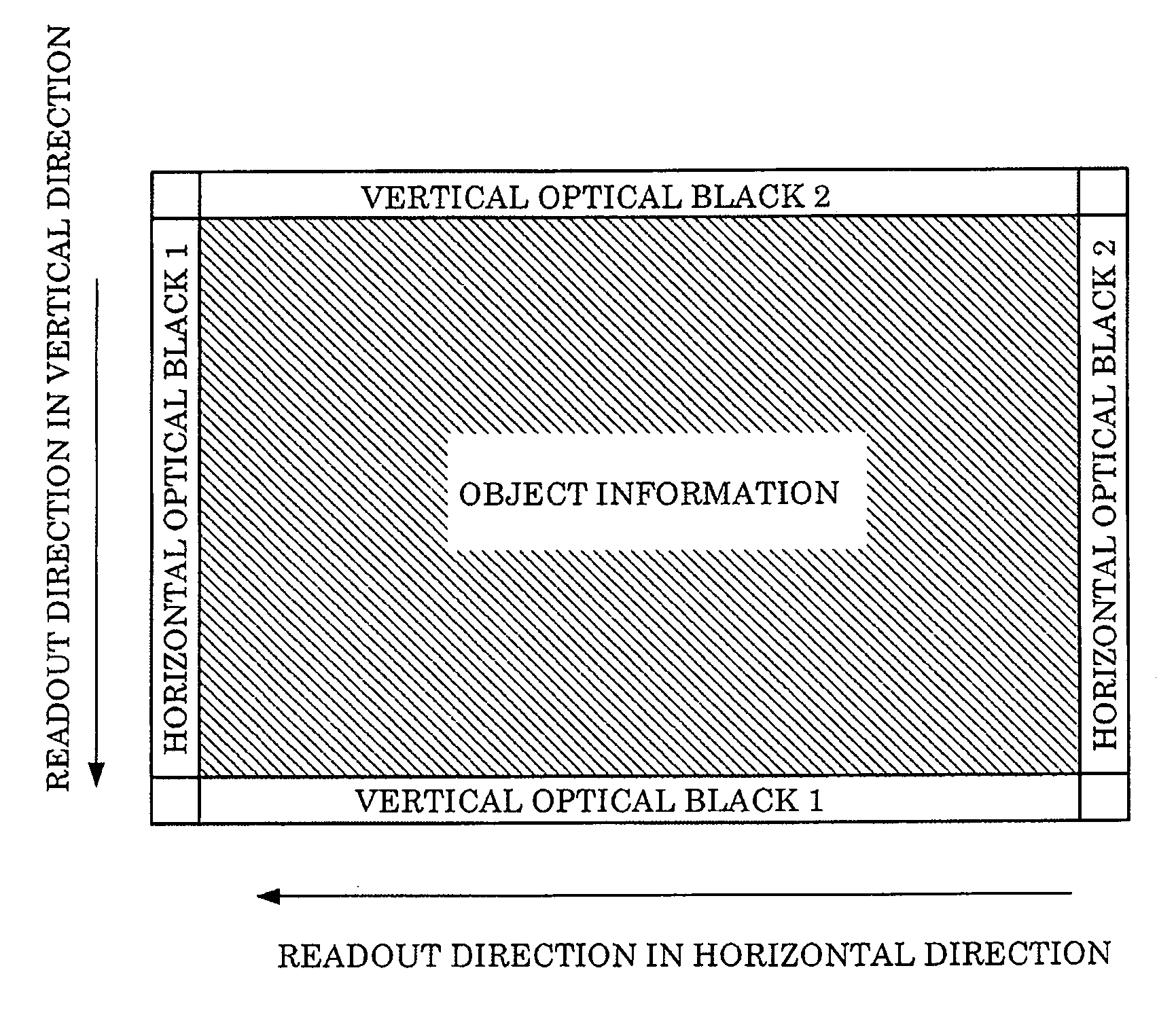
[0132] As shown in FIG. 10A, when a camera is turned laterally in the middle of imaging a high luminance object such as sunlight or car headlight by the CCD 5, smear is diagonally generated.

[0133] In this case, the position of a pixel where smear is generated in the vertical optical black region 1 does not vertically correspond with but is deviated laterally from the position of a pixel where smear is generated in the vertical optical black region...


PUM


Abstract

A horizontal evaluation data generation section calculates an average value of pixel signals in a vertical optical black region based on given pixel data in the horizontal optical black region and outputs the calculated average value to an evaluation section. A vertical evaluation data generation section calculates an average value of pixel signals in a vertical optical black region based on given pixel data in the vertical optical black region and outputs the calculated average value to the evaluation section. The evaluation section outputs a gain value according to the difference between the two sent average values to a computing section. A smear information memory stores pixel signals in a line in the vertical optical black region. The computing section multiplies the pixel data stored in the smear information memory by the sent gain value, and subtracts the multiplied pixel data from the pixel data imaged by the CCD 5.

Description

CROSS-REFERENCE TO RELATED APPLICATION [0001] This application is based upon and claims the benefit of priority from the prior Japanese Patent Application No. 2005-146647, filed May 19, 2005, the entire contents of which is incorporated herein by reference. BACKGROUND OF THE INVENTION [0002] 1. Field of the Invention [0003] The present invention relates to a digital camera comprising a smear removal function, more particularly to a digital camera which can change presence of smear removal or intensity of smear removal according to the smear generation state. [0004] 2. Description of the Related Art [0005] For the past number of years, in image pickup devices such as a CCD, there has been a problem that a white line called smear is generated in the imaged image data due to entrance of intense light (for example, sunlight, car headlight and the like), leading to deteriorated image quality. [0006] In order to solve such a problem, there have been digital cameras which remove smear by s...

Claims


Application Information

Patent Timeline
Patent Type & Authority Applications(United States)
IPC IPC(8): H04N5/228H01L27/148H04N5/335H04N5/341H04N5/359H04N5/369H04N5/372
CPCH04N5/3595H01L27/14623H04N25/625H04N23/40H04N25/60
Inventor YOSHIDA, TOSHIHIKOKUROSAWA, KAZUYUKI
Owner CASIO COMPUTER CO LTD
Why Eureka
Try Eureka