
Optical pickup device and recording and/or reproducing apparatus

a pickup device and optical pickup technology, applied in the field of optical pickup devices and recording and/or reproducing apparatus, can solve the problems of difficult manufacture of optical pickup devices, inability to use a case in which a reflective film, such as aluminum films, can be used, and achieve the effect of accurately detected and controlled accurately

Inactive Publication Date: 2006-12-07
SONY CORP
View PDF6 Cites 16 Cited by
  • Summary
  • Abstract
  • Description
  • Claims
  • Application Information

AI Technical Summary

Benefits of technology

The present invention provides an optical pickup device and a recording and / or reproducing apparatus that can accurately detect and control the gap between the optical recording medium and the solid immersion lens for improved performance. The device includes an objective lens, a solid immersion lens made up of a spherical portion and a flat portion parallel to the surface of the optical recording medium, and a photodetector means for detecting the reflected light from the medium. The device can adjust the position of the solid immersion lens to maintain the optimal distance between the medium and the lens for reading and writing information signals. The invention also provides a method for detecting the gap between the medium and the lens and controlling the position of the lens to maintain the optimal gap for recording and reproducing information.

Problems solved by technology

This, however, complicates the apparatus to render the manufacture of the optical pickup device difficult.
This method, however, cannot be used for a case in which a reflective film, such as an aluminum film, a phase change film or a photomagnetic recording film, is formed on the disc surface, as in an optical disc, because the light then undergoes reflection on the optical disc surface, even though the gap between the disc and the solid immersion lens is zero.

Method used


Image

  • Optical pickup device and recording and/or reproducing apparatus
  • Optical pickup device and recording and/or reproducing apparatus
  • Optical pickup device and recording and/or reproducing apparatus

Examples


Embodiment Construction

[0037] Referring to the drawings, certain preferred embodiments of the present invention will be explained in detail.

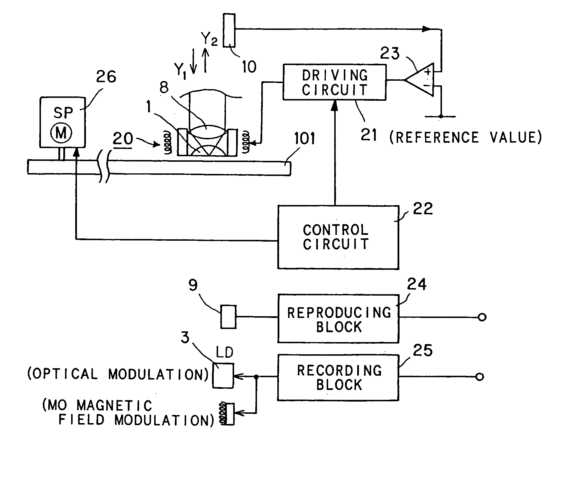
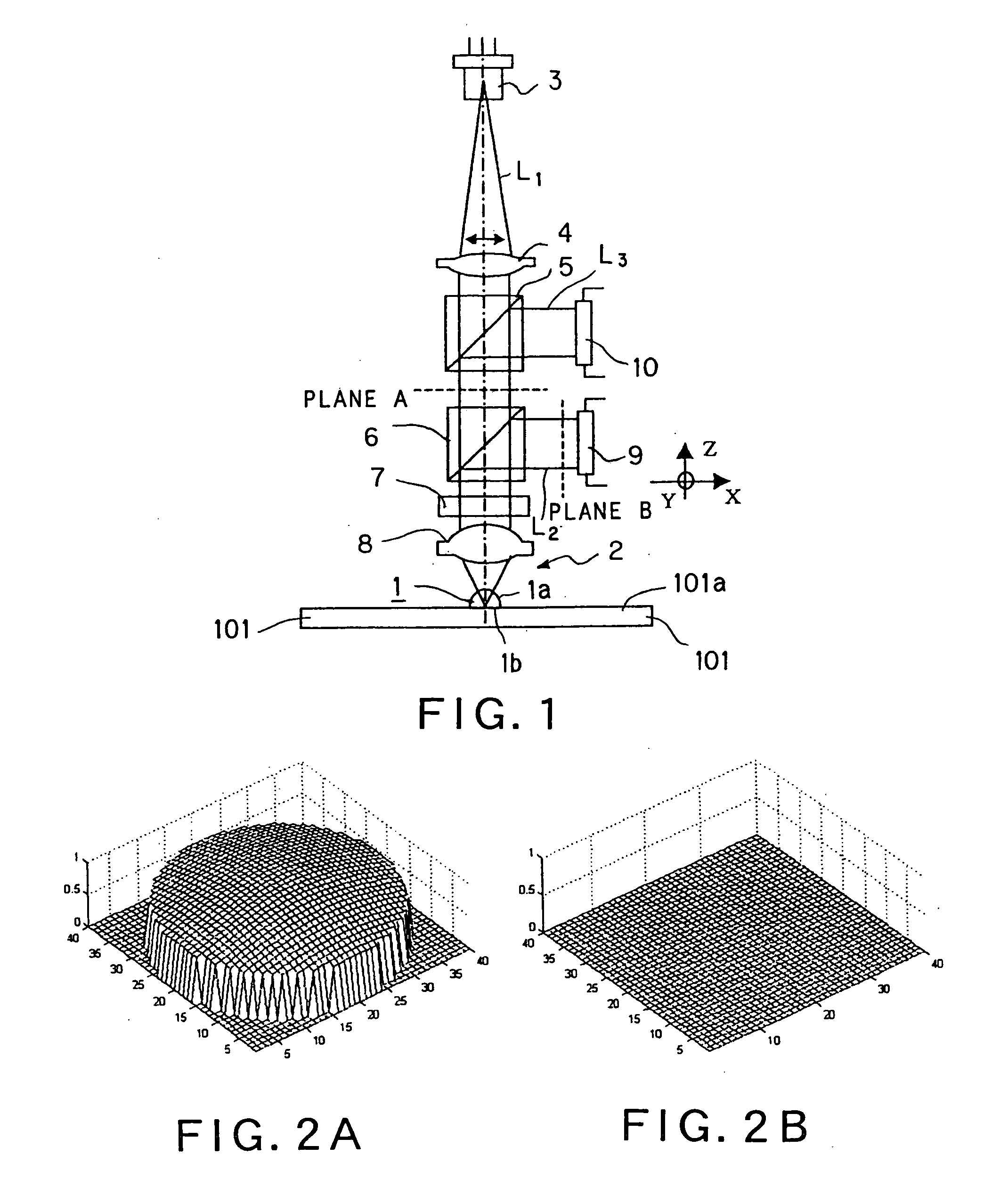
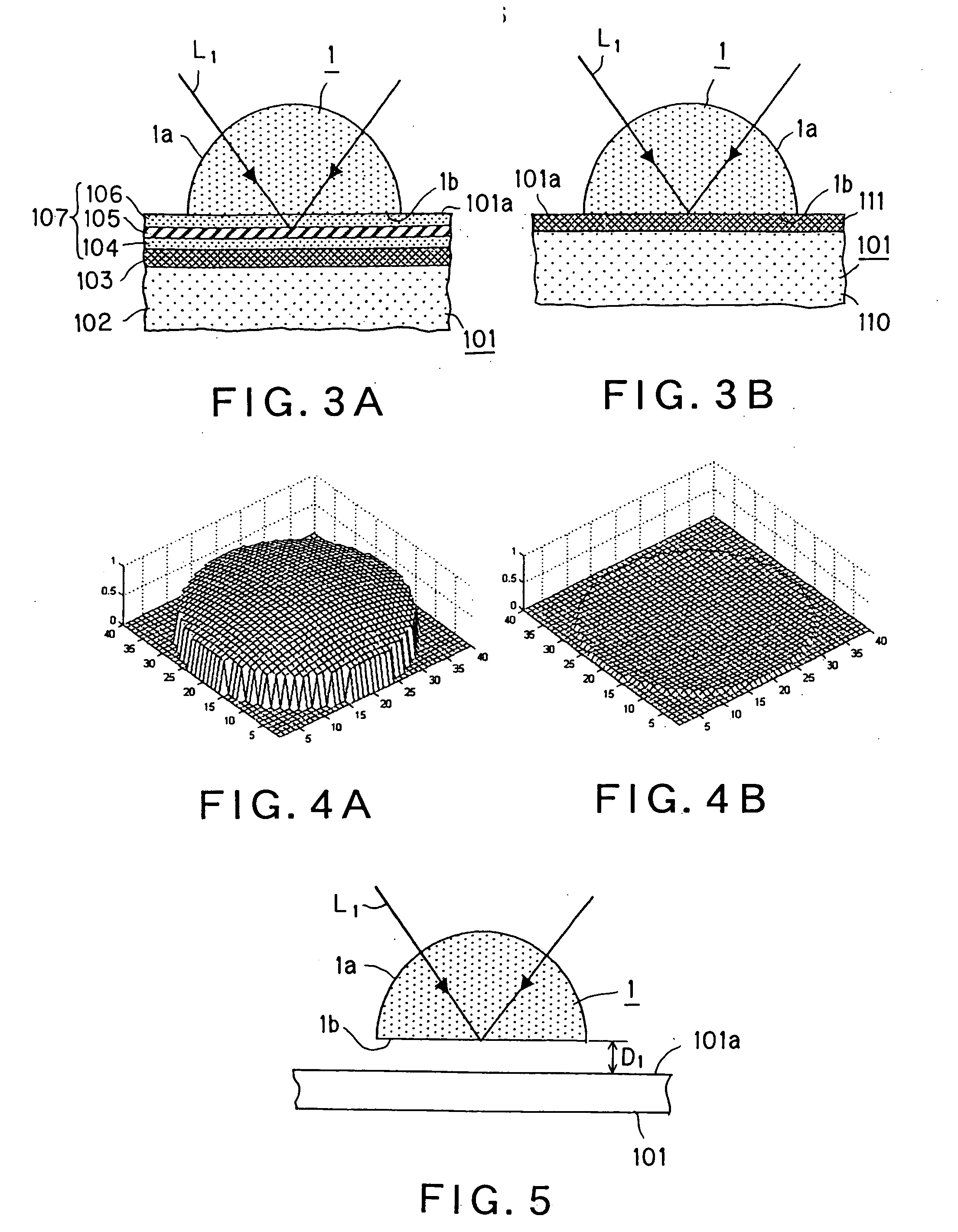
[0038] Referring to FIG. 1, an optical pickup device according to the present invention comprises an objective lens 2 including a solid immersion lens 1, with the numerical aperture (NA) being not less than 1. The solid immersion lens 1 includes a spherical surface portion 1a forming a portion of a sphere and a flat portion 1b facing a surface 101a of an optical disc 101 parallel thereto.

[0039] A distance (gap) G1 between the flat portion 1b of the solid immersion lens 1 forming the objective lens 2 and the surface 101a of the optical disc 101 as an optical recording medium is controlled, by control means provided in the optical pickup device according to the present invention, so as to be a distance G1 on the order of one-tenth of the wavelength λ of a light beam radiated from a semiconductor laser 3 as a light source. The optical pickup device of the present inven...


PUM

PropertyMeasurementUnit
wavelengthaaaaaaaaaa
refractive indexaaaaaaaaaa

Abstract

An optical pickup device includes an objective lens (2), with a numerical aperture (NA) being not less than 1, having a solid immersion lens (1) which is made up by a spherical portion (1a) and a flat portion (1b) parallel to a surface (101a) of an optical disc (101). The component of the reflected light from the optical disc in the polarized state perpendicular to the polarized state of the reflected light which prevails when the distance between the surface of the optical disc and the flat portion of the solid immersion lens is zero is detected. The so detected light intensity is associated with the distance between the optical disc surface and the solid immersion lens to accurately detect the minute gap between the optical disc and the solid immersion lens.

Description

CROSS-REFERENCE TO RELATED APPLICATIONS [0001] This application is a continuation of and is based upon and claims the benefit of priority under 35 U.S.C. §120 for U.S. Ser. No. 10 / 415,103, filed Apr. 30, 2003, and claims the benefit of priority under 35 U.S.C. § 119 from a PCT Application No. PCT / JP02 / 08627, filed Aug. 27, 2002, the entire contents of each which are incorporated herein by reference.TECHNICAL FIELD [0002] This invention relates to an optical pickup device for reading out information signals recorded on an optical recording medium, such as an optical disc, and to a recording and / or reproducing apparatus provided with this optical pickup device. More particularly, it relates to an optical pickup device and a recording and / or reproducing apparatus configured for controlling the distance between an objective lens of the optical pickup device and an optical recording medium. BACKGROUND ART [0003] Currently, a large variety of optical recording mediums are in use. Typical ...

Claims


Application Information

Patent Timeline
Patent Type & Authority Applications(United States)
IPC IPC(8): G11B11/00G11B7/00G11B7/1374G11B7/09
CPCB82Y10/00G11B7/0908G11B7/1356G11B7/1365G11B2007/13727G11B7/1387G11B7/139G11B11/10576G11B7/1374G11B7/09
Inventor SAITO, KIMIHIROISHIMOTO, TSUTOMU
Owner SONY CORP
Learn More