Support Fixture and Method for Supporting Subscriber Specific Fiber Optic Drop Wire

Inactive Publication Date: 2006-12-07
FORRESTER JOSEPH
View PDF13 Cites 12 Cited by
  • Summary
  • Abstract
  • Description
  • Claims
  • Application Information

AI Technical Summary

Benefits of technology

[0014] An object of the invention is to simplify the routing of drop cables from a cable closure. Another

Problems solved by technology

However, prior devices specifically intended for fiber optic cable are not necessarily applicable to fiber optic drop wire, which has only recently been put into use.
The reverse point of the fiber opt

Method used


Image

  • Support Fixture and Method for Supporting Subscriber Specific Fiber Optic Drop Wire
  • Support Fixture and Method for Supporting Subscriber Specific Fiber Optic Drop Wire
  • Support Fixture and Method for Supporting Subscriber Specific Fiber Optic Drop Wire

Examples


Embodiment Construction

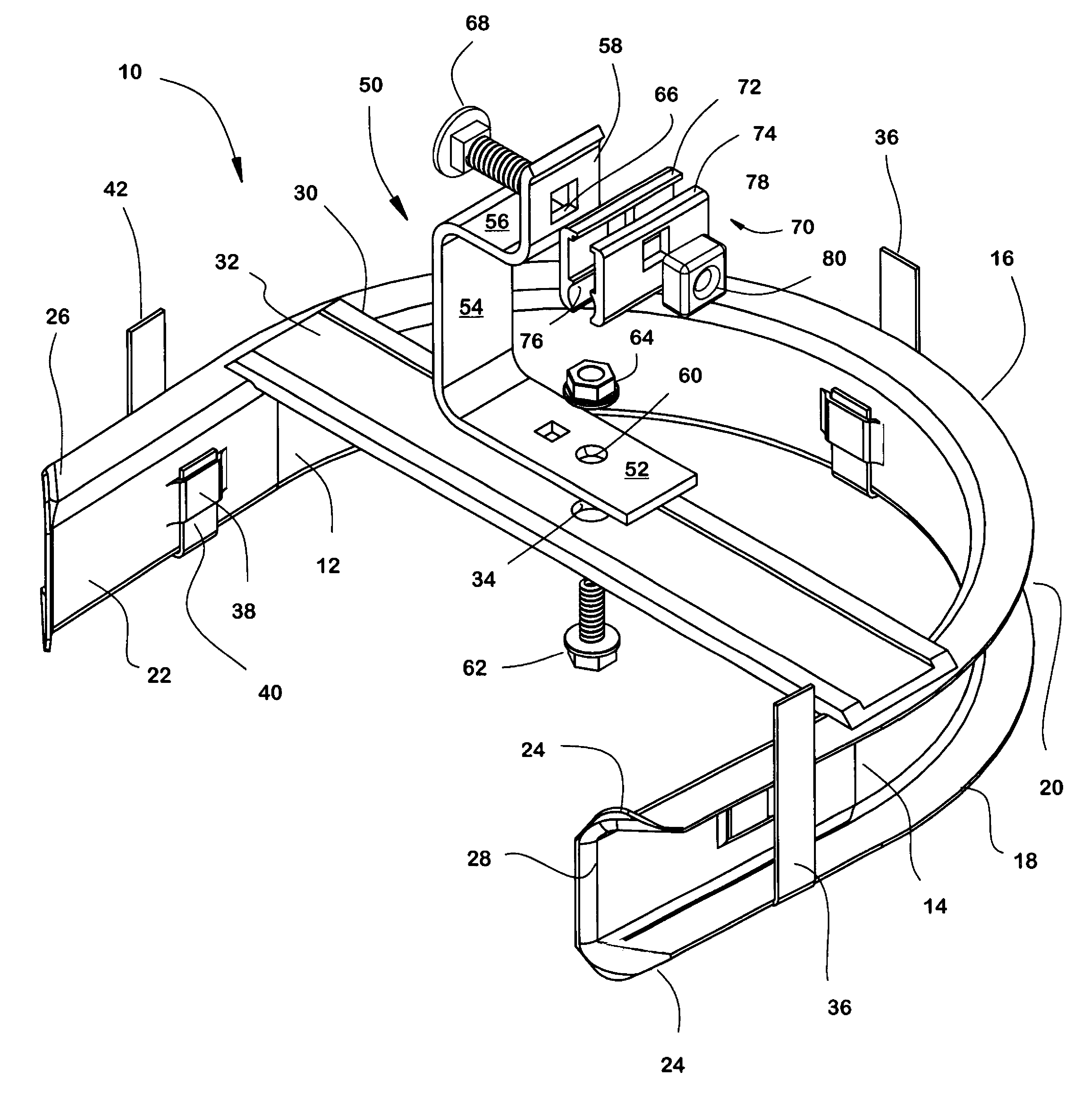
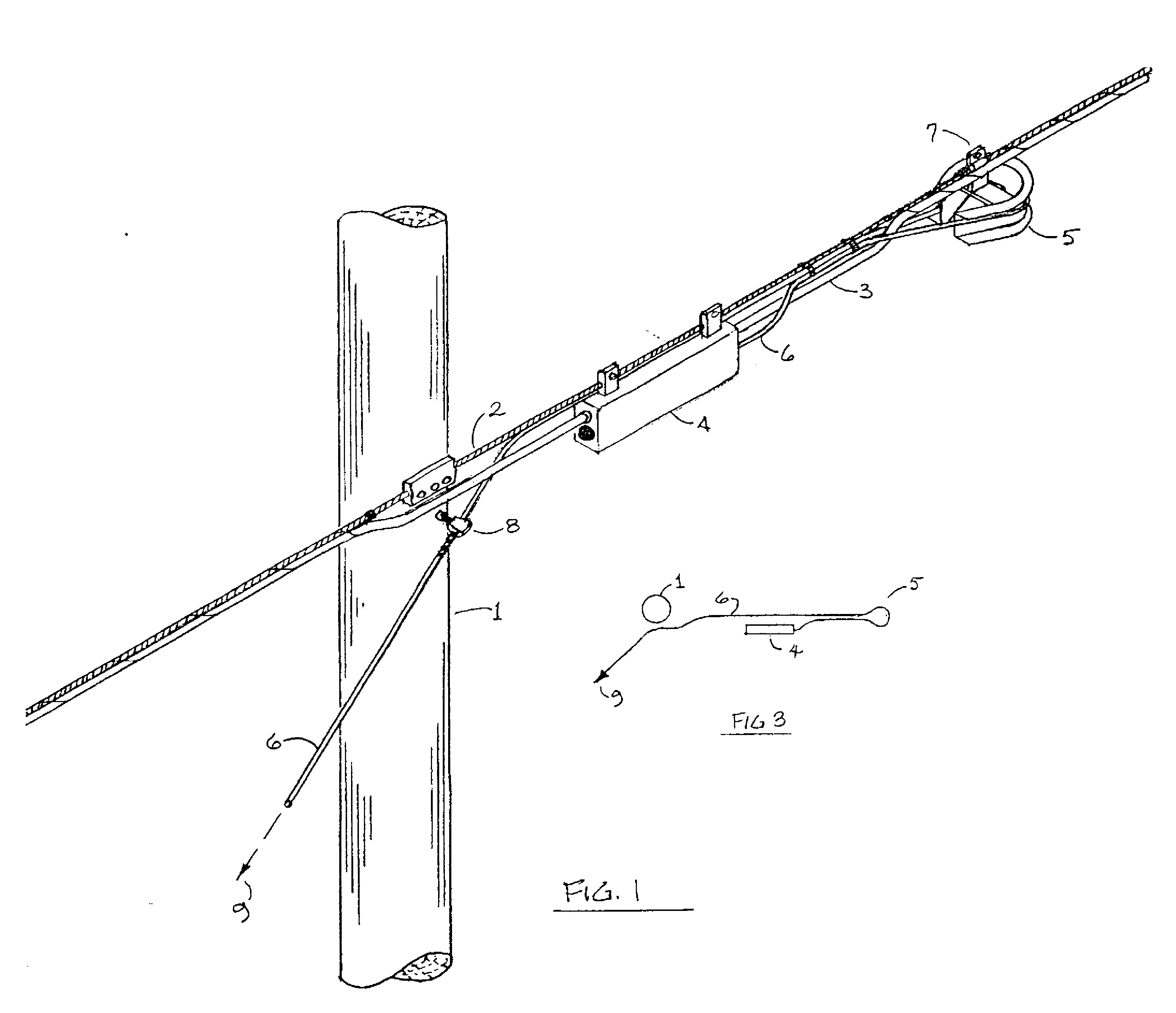
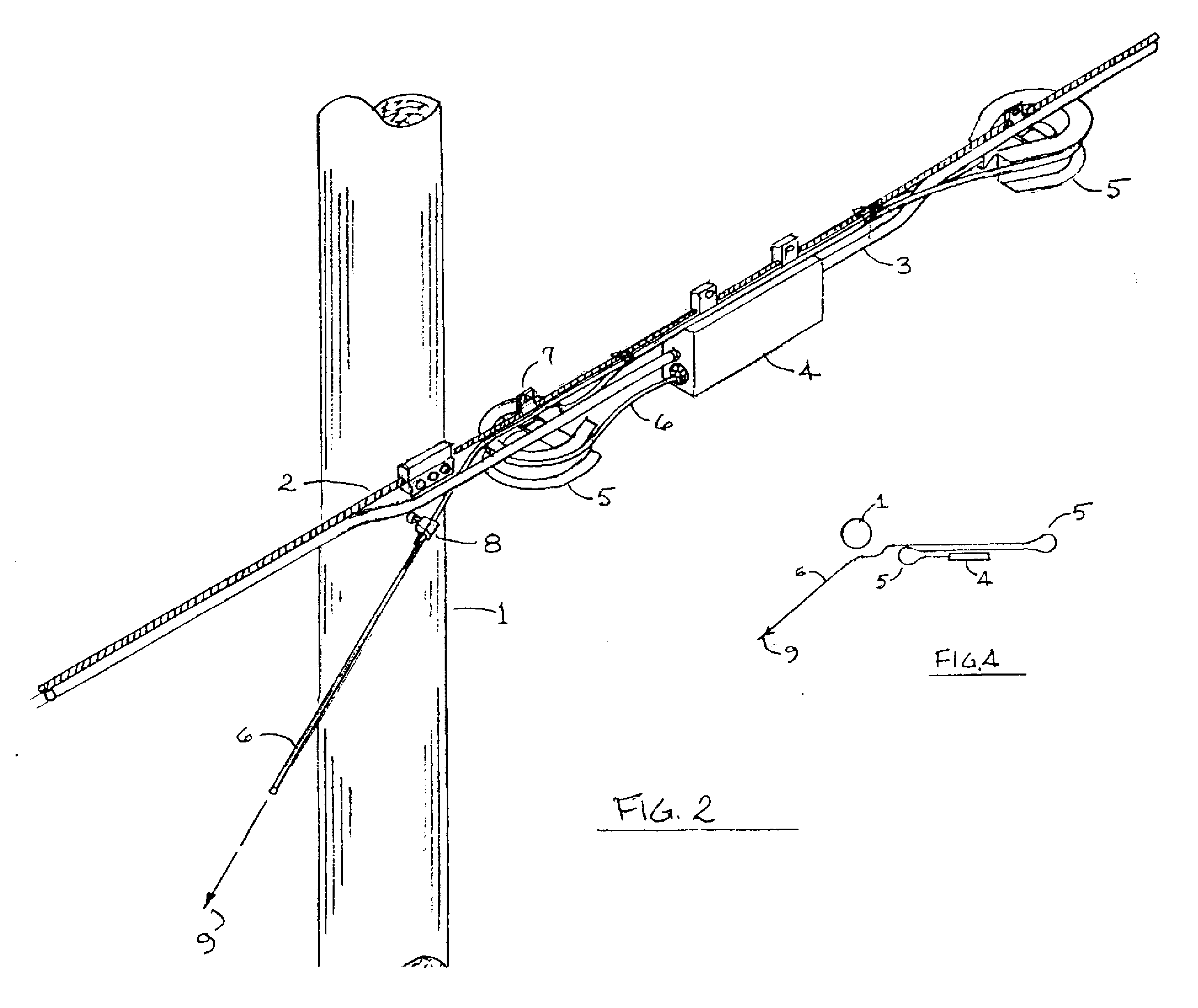
[0034] A fixture embodying the invention, shown in FIG. 1, includes a horseshoe-shaped bend radius protector 5 having two flanges defining an external channel for containing plural fiber optic drop wires. The protector 5 is suspended by a bracket 7 from a steel messenger cable 2 which is secured to a pole 1 by a clamp. A fiber optic cable 3 running along the messenger is secured to the messenger cable by wrapping. The cable closure 4 contains optical connectors which pass signal from the main cable to one or more drop wires 6. In most cases, three to sixteen drop wires extend from each cable closure; however, only one is shown in the drawing for the sake of clarity. The external channel of each bend radius protector is large enough to support from three to sixteen drop wires.

[0035] The cable closure has two ends: one near the pole and one further away. In the arrangement of FIG. 1, a drop wire extends from the further end in a direction away from the pole. It is tied to the messeng...


PUM


Abstract

Fiber optic drop wires extending from a cable closure supported along a fiber optic cable are supported by small horseshoe-shaped bend radius protectors which not only prevent overbending of the drop wires, but also enable one to store excess drop wire length on the bend radius protectors. The drop wire is secured in the channel of the bend radius protector by a retainer which has a hinge connection to the channel at one end and a latching detent portion at the other end, so that the retainer can be released when it is necessary to rerout or replace the drop wires.

Description

[0001] This application is a continuation-in-part of copending application Ser. No. 11 / 316185, filed Dec. 22, 2005, which was a continuation-in-part of copending application Ser. No. 10 / 829458, filed Apr. 22, 2004.BACKGROUND OF THE INVENTION [0002] This invention relates to a support fixture and method for supporting subscriber specific fiber optic drop wire. [0003] The invention relates generally to a method of aerially supporting lengths of fiber optic drop wire for subscriber applications, and more specifically, to an apparatus for supporting multiple lengths of fiber optic drop wire while maintaining a specified minimum bend radius. [0004] Devices for aerially supporting surplus lengths of fiber optic cable and apparatus designed to maintain a minimum specified bend radius for such cable are well known. However, prior devices specifically intended for fiber optic cable are not necessarily applicable to fiber optic drop wire, which has only recently been put into use. [0005] Whil...

Claims


Application Information

Patent Timeline
IPC IPC(8): G02B6/00G02B6/48
CPCG02B6/483
Inventor FORRESTER, JOSEPH
Owner FORRESTER JOSEPH
Why Eureka
Try Eureka