Visibility adjusting method and apparatus of vehicle

a technology of visibility adjustment and apparatus, applied in the direction of windows, roofs, transportation and packaging, etc., can solve the problems of increased fatigue, decreased visibility, and decreased stability of the position, so as to suppress the sway of the head inclination angle, the effect of reducing the visibility of the windshield and reducing fatigu

Inactive Publication Date: 2006-12-07
NISSAN MOTOR CO LTD
View PDF12 Cites 3 Cited by
  • Summary
  • Abstract
  • Description
  • Claims
  • Application Information

AI Technical Summary

Benefits of technology

[0009] To achieve the above object, the present invention provides a visibility adjusting method of a vehicle in which a windshield is provided at its lower end with a visibility adjusting section to adjust forward visibility of a driver, comprising the steps of: disposing an apex at a position deviated from the driver and between a position opposed to the driver and a vehicle center position; setting left and right ridgelines which uniformly incline downwardly from the apex toward opposite sides in a vehicle-width direction; and forming a visibility adjusting section by the apex and the left and right ridgelines as a parting line which adjusts a lower end visibility of the windshield.
[0010] According to the present invention, the parting line of the visibility adjusting section provided on the lower end of the windshield is uniformly and downwardly inclined from the apex disposed at a position deviated from the driver toward the opposite sides in the vehicle-width direction. Therefore, the sense of balance of the driver can be stabilized by this inclined parting line and the sway of the head inclination angle can be suppressed. Thus, the driver's posture is stabilized and the steering disturbance can be suppressed.

Problems solved by technology

That is, if the visibility immediately in front of the vehicle is excessively excellent, the driver's nerve is worn and fatigue is increased.
However, it is found that this position is not always stabilized and is varied.
As a result of this variation, the driver's posture becomes unstable and with this, steering operation is disturbed, and this causes a vicious circle that this steering disturbance varies the turning lateral acceleration and the head inclination angle becomes further unstable.
That is, it is known that when one losses a horizontal degree of a reference line, he or she losses sense of balance.
As a result, it is confirmed that the sway of the window frame lower end line at the time of rolling visually disturbs the sense of balance and affects the head inclination angle.

Method used


Image

  • Visibility adjusting method and apparatus of vehicle
  • Visibility adjusting method and apparatus of vehicle
  • Visibility adjusting method and apparatus of vehicle

Examples


first embodiment

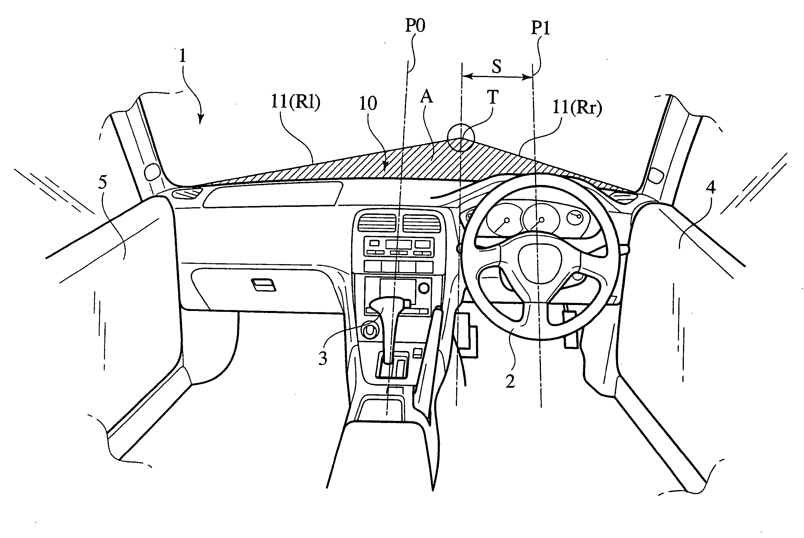
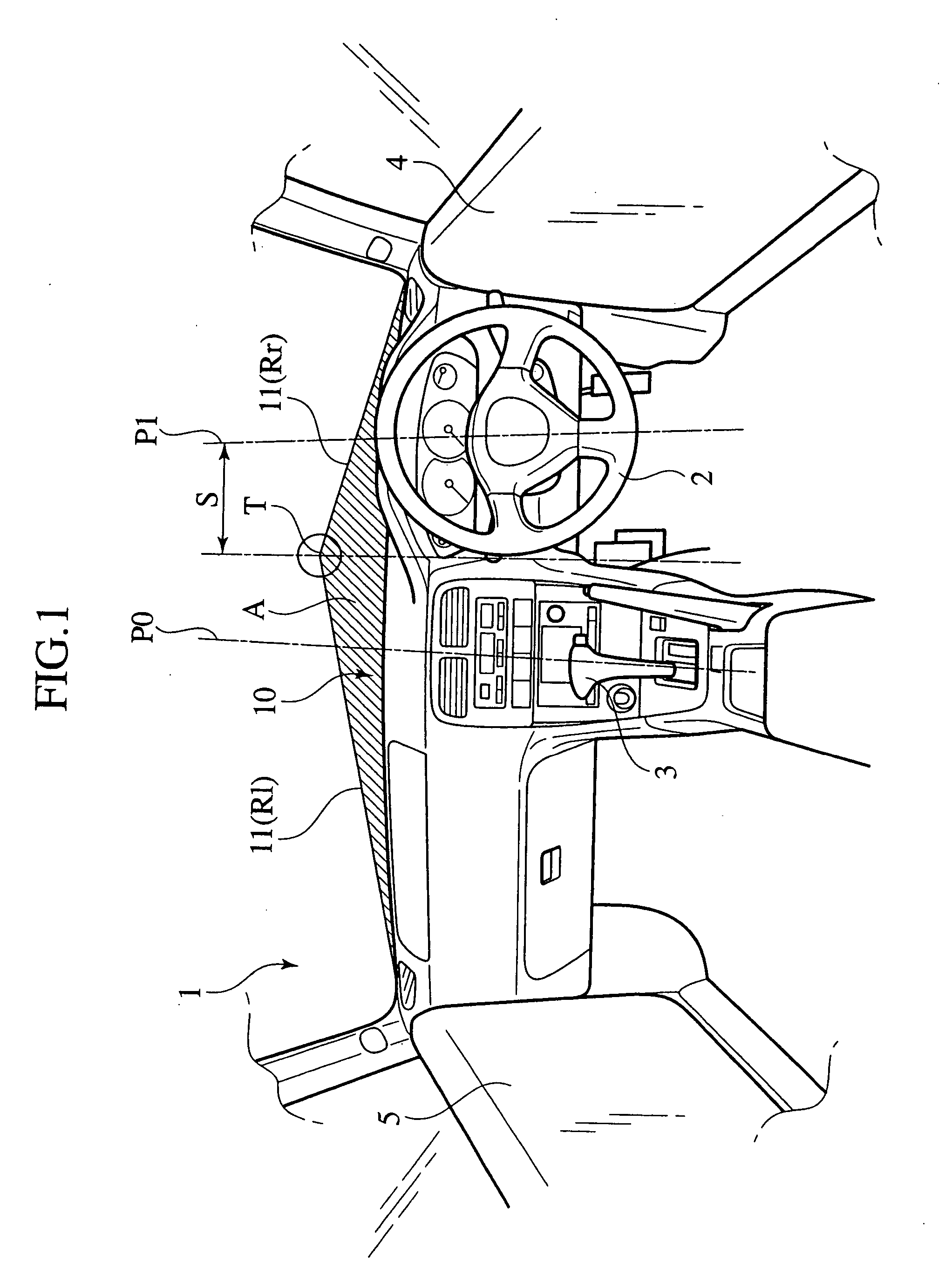
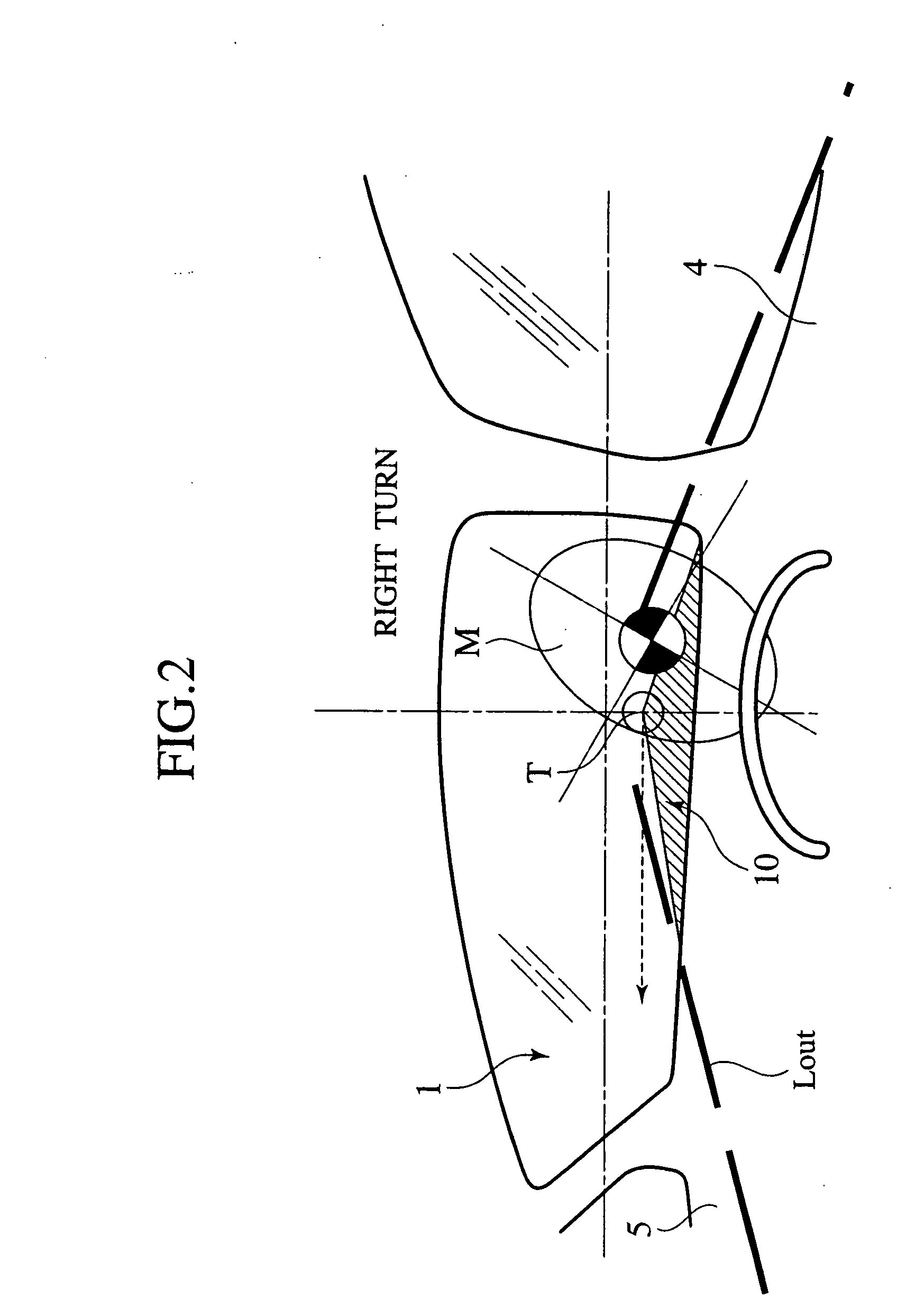
[0035] FIGS. 1 to 6 show a first embodiment of a visibility adjusting method of a vehicle according to the invention. FIG. 1 is a perspective view of a vehicle as viewed forwardly from inside of the vehicle, FIG. 2 is an explanatory view showing a relation between a parting line and forward visibility as viewed from a driver, FIG. 3 is an explanatory view showing a relation between a line of vision of the driver and the apex of the parting line, FIG. 4 is an explanatory view showing a forward visibility when making a right turn, FIGS. 5A and 5B show a relation between a head angle and a pendulum angle when the vehicle turns, and FIG. 6 is a graph showing a relation of relative frequencies indicative of steering disturbance with respect to the steering speed distribution.

[0036] According to the visibility adjusting method of a vehicle in the first embodiment, as shown in FIGS. 1 to 3, a windshield 1 is provided at its lower end with a visibility adjusting section 10 by which a forwa...

second embodiment

[0050]FIG. 7 shows a second embodiment. The same constituent portions as those in the first embodiment are designated with the same symbols and redundant explanation will be omitted. FIG. 7 is a perspective view of the vehicle as viewed forwardly from inside of the vehicle.

[0051] As shown in FIG. 7, according to the visibility adjusting method of a vehicle of the second embodiment, the parting line 11 of a visibility adjusting section 10a is displaced in accordance with a vehicle orientation and / or a vehicle acceleration.

[0052] That is, according to the visibility adjusting section 10a of this embodiment, as shown in FIG. 7, the lower end of the windshield 1 is provided with a movable plate 12 extending in the vehicle-width direction, and the movable plate 12 is mounted on the vehicle body such that the movable plate 12 can swing laterally and an intermediate portion of the movable plate 12 functions as a fulcrum 12f. A mass body 12w which is integral with the movable plate 12 is ...

third embodiment

[0058]FIGS. 8 and 9 show a third embodiment of the invention. The same constituent portions as those in the first embodiment are designated with the same symbols and redundant explanation will be omitted. FIG. 8 is a perspective view of the vehicle as viewed forwardly from inside of the vehicle, and FIG. 9 is a perspective view of the windshield portion as viewed from front of the vehicle.

[0059] According to the visibility adjusting method of the vehicle of the third embodiment, as shown in FIG. 8, a visibility adjusting section 10b is a shielding plate 13 formed along a shape of a region A lower than the parting line 11.

[0060] At that time, the shielding plate 13 is made of flexible plate material so that the shielding plate 13 can be impregnated along the curve shape of the windshield 1. For example, a black film sheet can be used.

[0061] In this embodiment, as shown in FIG. 9, an adornment D is added on one surface (outer surface) of the shielding plate 13.

[0062] With this con...


PUM


Abstract

According to a visibility adjusting apparatus of a vehicle, an apex T is disposed at a position deviated from a driver and between a position opposed to the driver and a vehicle center position, left and right ridgelines uniformly downwardly inclined from the apex T to the vehicle-width direction are set, and a visibility adjusting section is formed as a parting line which adjusts a lower end visibility of the windshield. The visibility adjusting section is formed of the apex and the left and right ridgelines. With this, a sense of balance of the driver can be stabilized by the inclined parting line, and the sway of a head inclination angle can be suppressed.

Description

BACKGROUND OF THE INVENTION [0001] The present invention relates to a visibility adjusting method and an apparatus for adjusting a driver's forward visibility by providing a lower end of a windshield with a visibility adjusting section. [0002] Conventionally, there is known a visibility adjusting method of a vehicle in which a lower end of a windshield is shielded, and the forward visibility is adjusted in accordance with a running state, thereby enhancing a forward visibility at driving as disclosed in Japanese Patent Application Laid-Open No. 2000-211355 for example. [0003] In such a conventional visibility adjusting method, an actual vehicle speed and a distance between vehicles are detected, and these values are compared with corresponding values of a calculation method so that the visibility is limited when running on an expressway to prevent fatigue and sleepiness, and sufficient visibility is secured during medium and low speed running to prevent the driver from overlooking a...

Claims


Application Information

Patent Timeline
Patent Type & Authority Applications(United States)
IPC IPC(8): H04B10/04B60J1/00B60J1/20
CPCB60J1/20
Inventor IWAO, KEIJIROITO, MITSUHITOUENUMA, KENYA
Owner NISSAN MOTOR CO LTD
Why Eureka
Try Eureka