Tire air pressure monitoring system

Active Publication Date: 2006-12-07
DENSO CORP
View PDF21 Cites 7 Cited by
  • Summary
  • Abstract
  • Description
  • Claims
  • Application Information

AI Technical Summary

Benefits of technology

[0016] Generally, the one tractor head will be selectively connected with the various trailers. However, according to the conventional tire air pressure monitoring system, the wheel identification information of the wheels of the new trailer is to be taken into the storage unit of the tire air pressure receiving apparatus

Problems solved by technology

Therefore, the construction of the trailer 102 for th

Method used


Image

  • Tire air pressure monitoring system
  • Tire air pressure monitoring system
  • Tire air pressure monitoring system

Examples


first embodiment

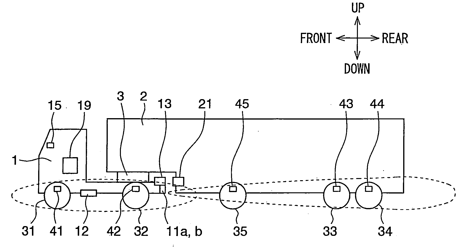
[0031] A tire air pressure monitoring system according to a first embodiment of the present invention will be described with reference to FIGS. 1-8. As shown in FIG. 1, the tire air pressure monitoring system can be suitably used for a vehicle which has a tractor head 1 (second member) and a trailer 2 (first member), for example.

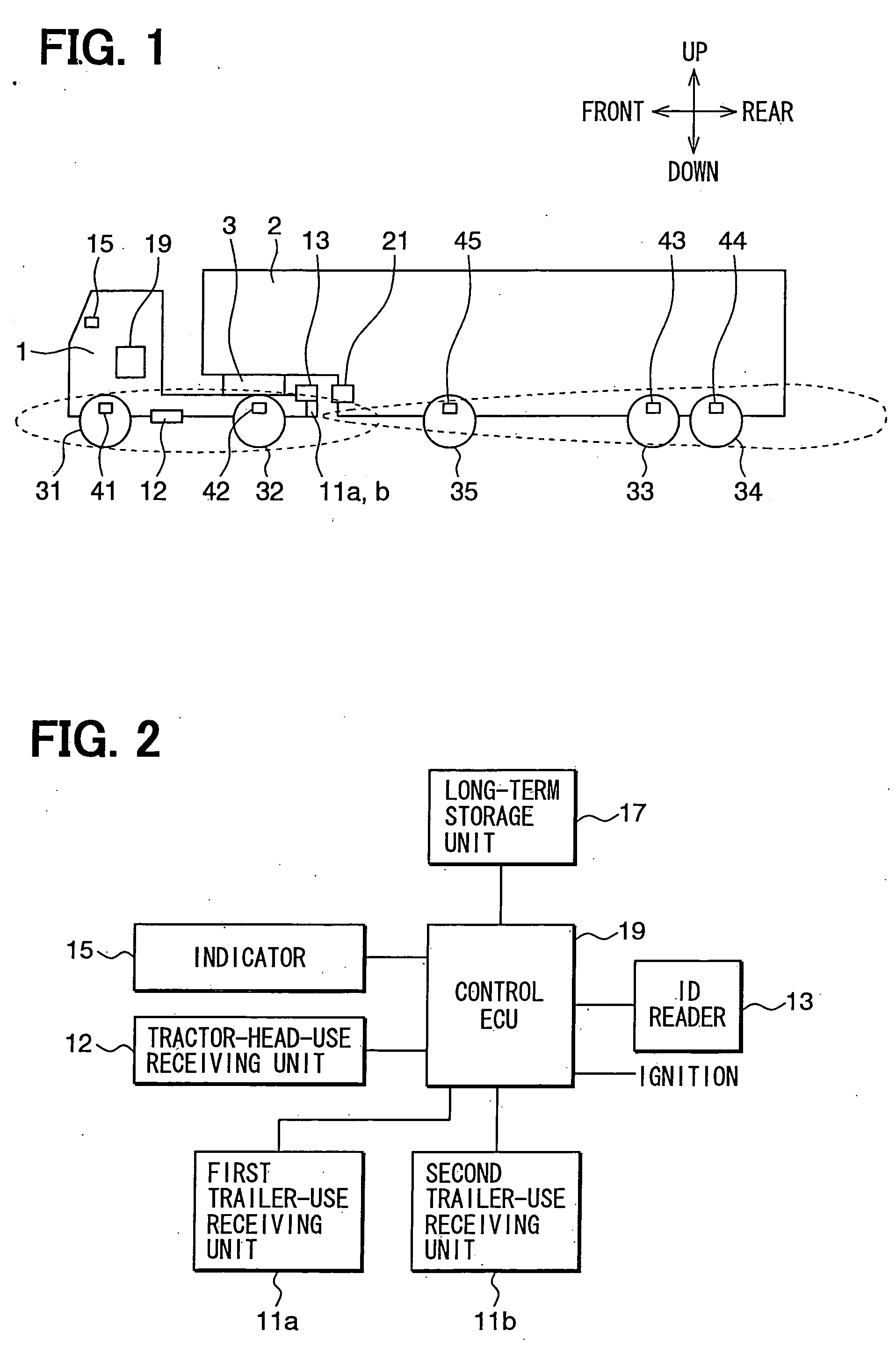
[0032] The trailer 2 is connected with the tractor head 1 at a connection portion 3 of the tractor head 1. FIG. 2 shows a construction and a connection relation of the part of the tire air pressure monitoring system which is mounted at a chassis of the tractor head 1.

[0033] Referring to FIG. 1, the tractor head 1 has multiple wheels, for example, a pair of wheels 31 which are respectively symmetrically arranged at a right front portion and a left front portion of the tractor head 1, and a pair of wheels 32 which are respectively symmetrically arranged at a right rear portion and a left rear portion of the tractor head 1. A vehicle (tractor head 1) left-rig...

second embodiment

[0074] A second embodiment of the present invention will be described with reference to FIGS. 9 and 10. FIG. 9 shows the construction of the tire air pressure monitoring system of the side of the tractor head 1. According to the second embodiment, the connection portion 3 of the tractor head 1 is provided with a connection detection unit 16. That is, the tire air pressure receiving apparatus of the tire air pressure monitoring system further includes the connection detection unit 16.

[0075] The connection detection unit 16 is attached to the connection portion 3, to detect whether or not the trailer 2 is connected with the tractor head 1 and output a detection result (as signal) to the control unit 19.

[0076] Alternatively, whether or not the trailer 2 is connected with the tractor head 1 can be also determined, by detecting a mechanical arrangement difference of the connection portion 3 between the case where the tractor head 1 is connected with the trailer 2 and the case where the...

third embodiment

[0084] A third embodiment of the present invention will be described with reference to FIG. 11.

[0085] In this embodiment, the CPU of the control unit 19 repeatedly performs an ID reading program 400 showing in FIG. 11 instead of the ID reading program 200. Referring to FIG. 11, at first, at step S405, the control unit 19 resets a timer for a predetermined time. Then, at step S410, the control unit 19 waits for an expiration of the timer. That is, the control unit 19 determines whether or not the predetermined time has elapsed.

[0086] In the case where it is determined that the predetermined time has elapsed, step S420 will be performed. At step S420, the CPU of the control unit 19 controls the ID reader 13 to obtain the ID (wheel identification information of wheels 33-35 of trailer 2) from the transponder 21. On the other hand, in the case where it is determined that the predetermined time has not elapsed, step S410 will be repeated.

[0087] After step S420, the obtained ID is over...


PUM


Abstract

A tire air pressure monitoring system is provided with at least one trailer-use receiving unit, which is mounted at a rear end of a tractor head to receive radio wave sent by multiple tire air pressure sending units. The tire air pressure sending units are respectively attached to wheels of a trailer. The trailer-use receiving unit, having a directional antenna, is oriented to have a stronger receiving sensitivity with respect to a direction of the trailer than other directions.

Description

CROSS REFERENCE TO RELATED APPLICATION [0001] This application is based on a Japanese Patent Application No. 2005-165597 filed on Jun. 6, 2005, the disclosure of which is incorporated herein by reference. FIELD OF THE INVENTION [0002] The present invention relates to a tire air pressure monitoring system. The tire air pressure monitoring system is suitably used for a vehicle, to monitor tire air pressures of wheels of a trailer of the vehicle at the side of a tractor head of the vehicle, for example. BACKGROUND OF THE INVENTION [0003] Generally, a tire air pressure monitoring system receives radio wave sent by a tire air pressure sending unit, which detects a tire air pressure and sends tire air pressure information by radio. The tire air pressure monitoring system acquires the tire air pressure information from the received radio wave. [0004] Referring FIG. 13, the tire air pressure monitoring system is used for a vehicle having a tractor head 101 and a trailer 102 which are connec...

Claims


Application Information

Patent Timeline
IPC IPC(8): G01L17/00
CPCB60C23/007B60C23/0408B60C23/009
Inventor WATABE, NOBUYA
Owner DENSO CORP
Why Eureka
Try Eureka