
Capacity-expanding memory device

a memory device and expansion technology, applied in the field of memory devices, can solve the problem of achieve the effect of expanding the memory capacity of a memory module and not increasing the load on the bus

Inactive Publication Date: 2006-12-07
SANMINA-SCI CORPORATION
View PDF59 Cites 120 Cited by
  • Summary
  • Abstract
  • Description
  • Claims
  • Application Information

AI Technical Summary

Benefits of technology

The invention describes how to increase the storage capacity of a computer chip by combining several small memories into one high-capacity memory. This happens without adding extra components or increasing the workload for the processor. Each component has its own unique address, which allows it to be controlled separately while still appearing like a single entity to the rest of the system. Overall, this technology helps improve performance and efficiency when dealing with large amounts of data.

Problems solved by technology

The technical problem described in this patent text relates to how to increase the amount of memory capacity within a given memory module design without exceeding industry standards or physically limiting the placement of components. Existing solutions involve either decreasing the size of individual memory cells or introducing complex hardware designs that improve performance but fail to provide significant improvements in overall memory capacity.

Method used


Image

  • Capacity-expanding memory device
  • Capacity-expanding memory device
  • Capacity-expanding memory device

Examples


Embodiment Construction

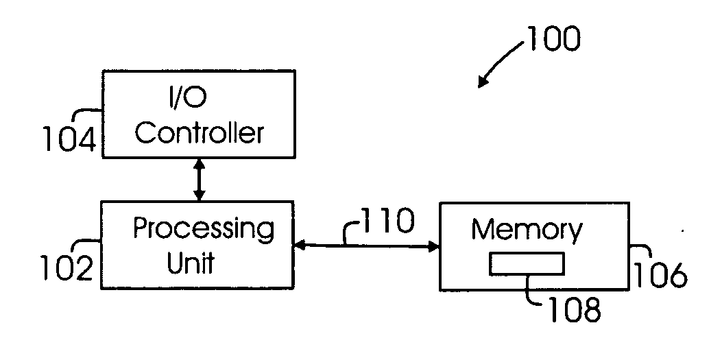
[0022] Methods and systems that implement the embodiments of the various features of the invention will now be described with reference to the drawings. The drawings and the associated descriptions are provided to illustrate embodiments of the invention and not to limit the scope of the invention. Reference in the specification to “one embodiment” or “an embodiment” is intended to indicate that a particular feature, structure, or characteristic described in connection with the embodiment is included in at least an embodiment of the invention. The appearances of the phrase “in one embodiment” or “an embodiment” in various places in the specification are not necessarily all referring to the same embodiment. Throughout the drawings, reference numbers are re-used to indicate correspondence between referenced elements. In addition, the first digit of each reference number indicates the figure in which the element first appears.

[0023] In the following description, certain terminology is ...


PUM


Abstract

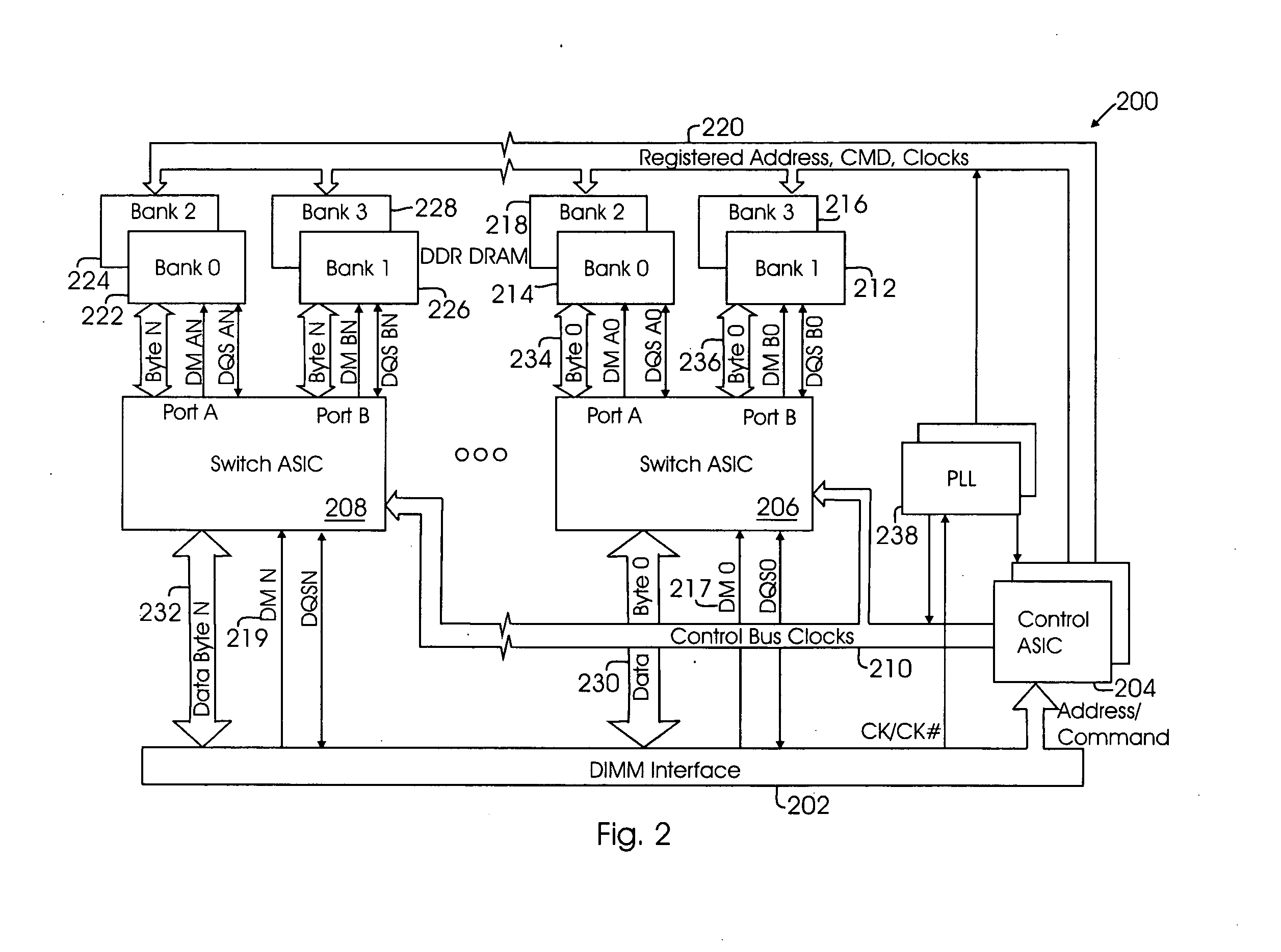
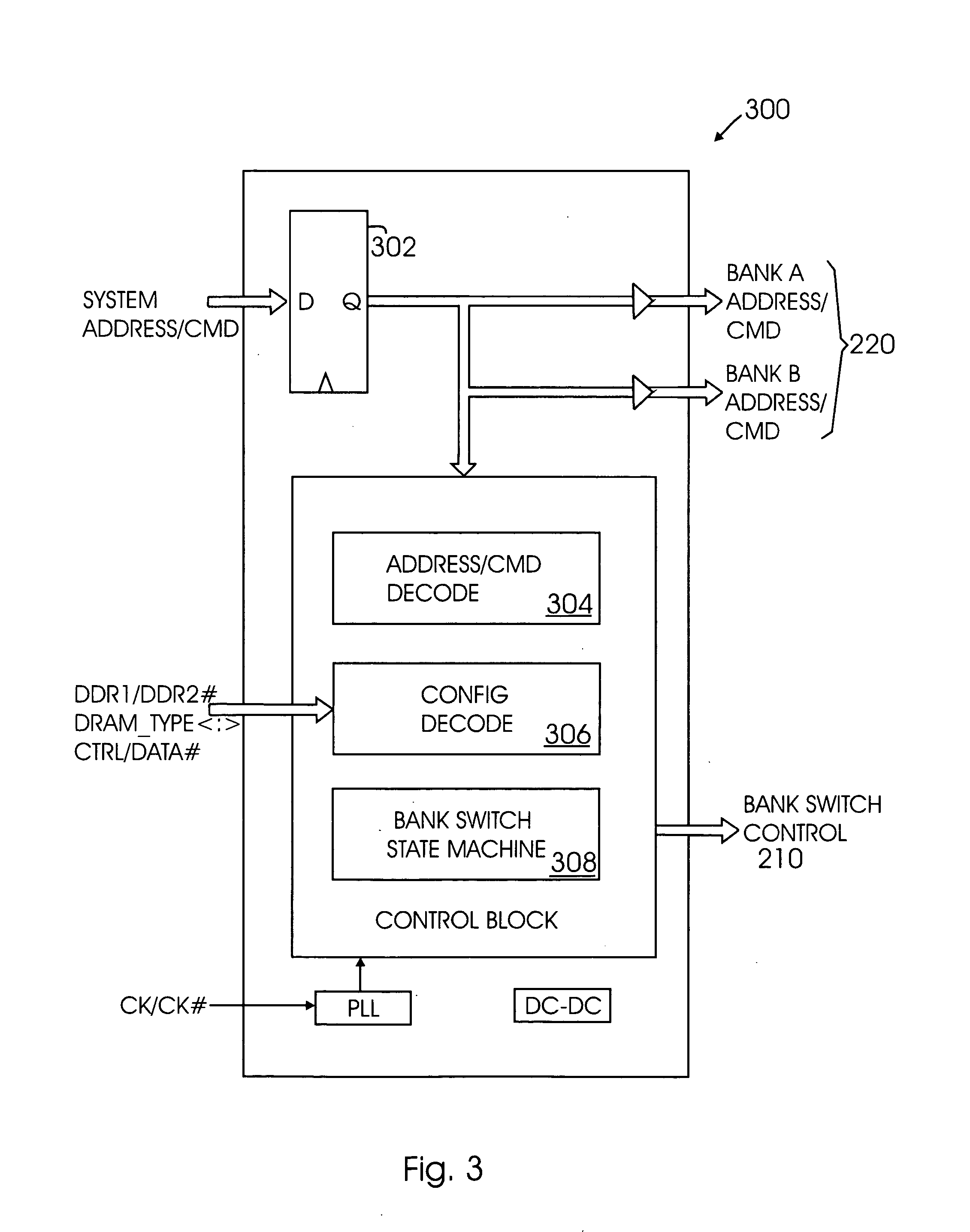
The invention relates to a device, system, and method for expanding the memory capacity of a memory module. A control unit and memory bank switch are mounted on a memory module to selectively control write and/or read operations to/from memory devices communicatively coupled to the memory bank switch. By selectively routing data to and from the memory devices, a plurality of memory devices may appear as a single memory device to the operating system. That is, the invention expands the addressable memory banks on a module by making two smaller-capacity memory devices emulate a single higher-capacity memory device.

Description


Claims


Application Information

Patent Timeline
Owner SANMINA-SCI CORPORATION
Learn More