System startup method

Inactive Publication Date: 2006-12-07
HITACHI LTD
View PDF4 Cites 26 Cited by
  • Summary
  • Abstract
  • Description
  • Claims
  • Application Information

AI Technical Summary

Benefits of technology

[0012] As a result of the increased number of times the user uses the system without any special instruction to the system, only functions that are suitable for the user are automatically started. This makes it possible to shorten the time taken to start functions that are not used by the user. Furthermo

Problems solved by technology

In the field of not only conventional personal computers but also home electric appliances, data processing capability increases year by year, and therefore systems become sophisticated and complicated.
As a result, a length of time required to start up each system is also increasing.
One bloated functi

Method used


Image

  • System startup method
  • System startup method
  • System startup method

Examples


first embodiment

[0028] A first embodiment relates to a system startup method according to the present invention. This embodiment will be described with reference to FIGS. 1 through 7 below.

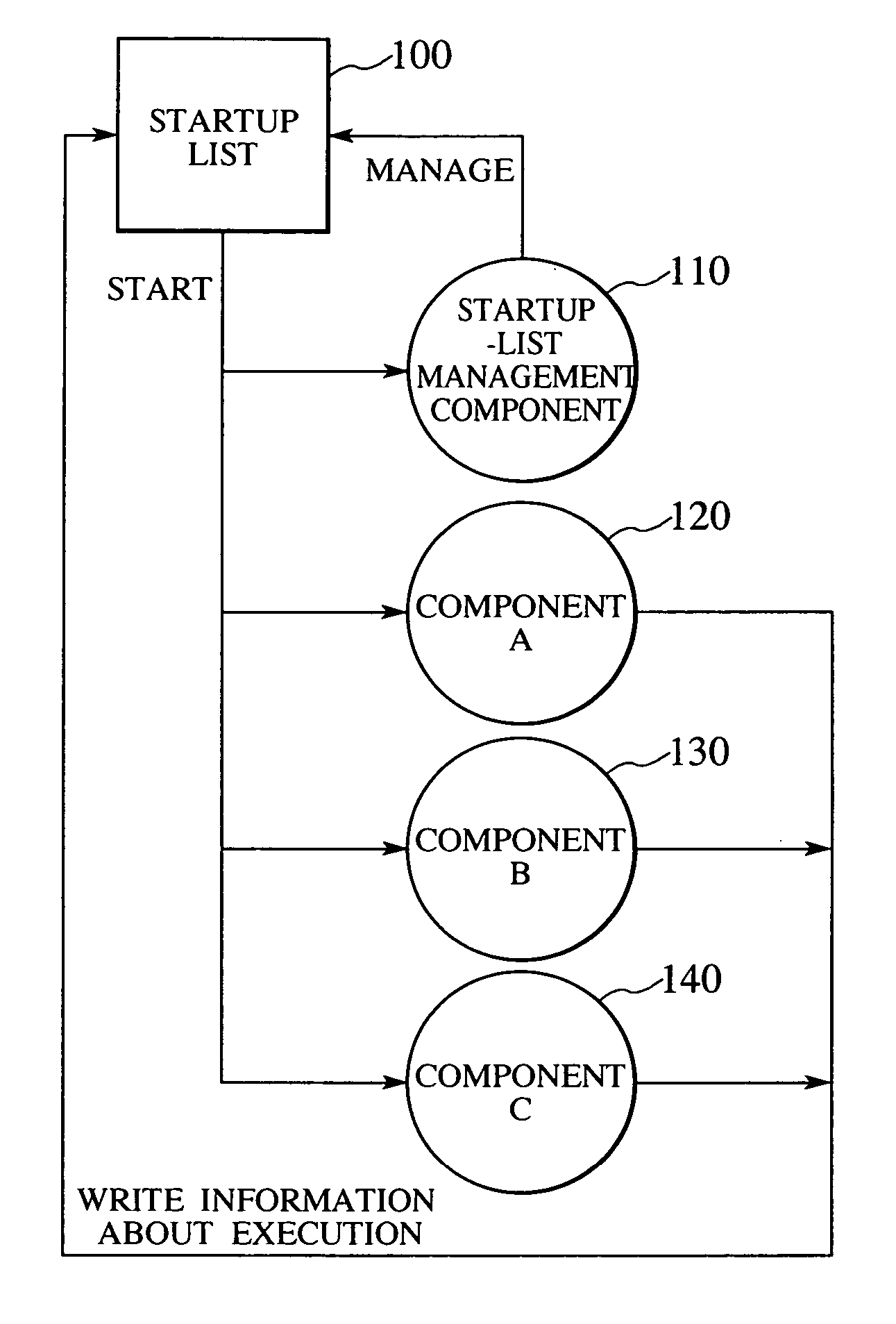
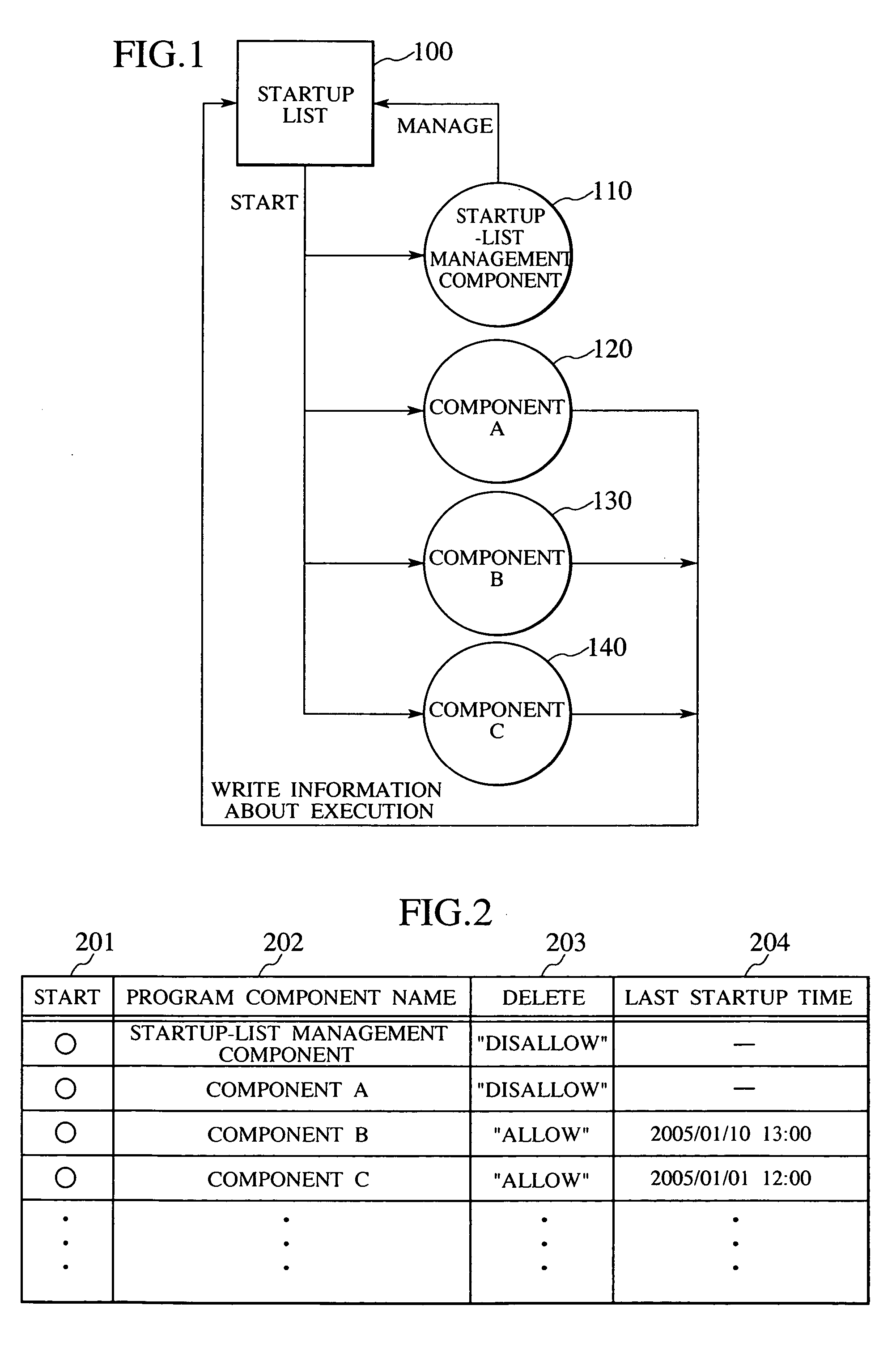
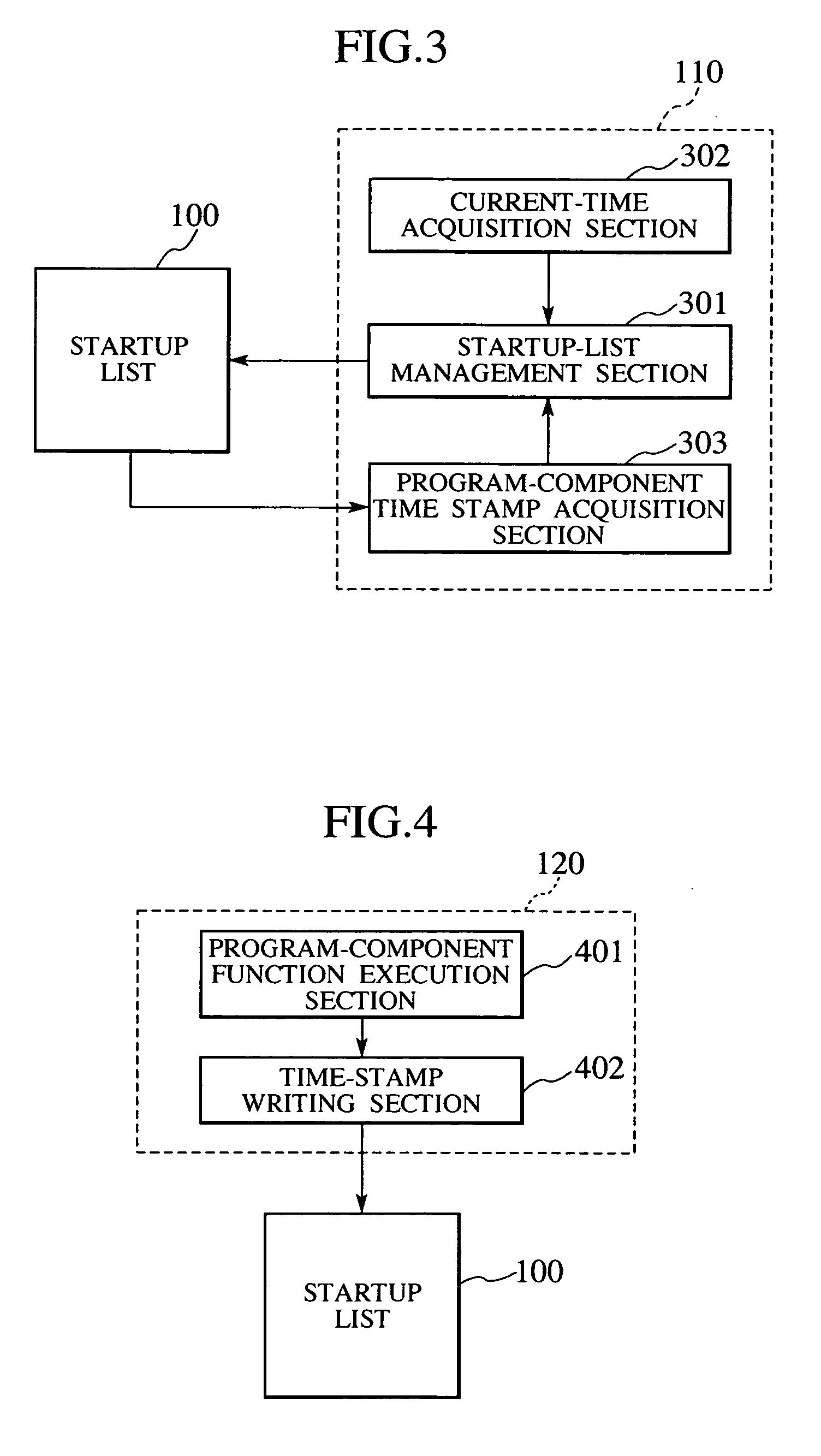
[0029]FIG. 1 is a diagram schematically illustrating a system startup method according to the present invention. FIG. 2 is a diagram illustrating a list of program components to be started at the time of system startup, and a startup list which describes information about each of the program components. FIG. 3 is a block diagram illustrating sections included in a startup-list management component shown in FIG. 1, and communications with the startup list. FIG. 4 is a block diagram illustrating sections included in a program component, and communications with the startup list. FIG. 5 is a flowchart illustrating processing steps performed at the time of system startup. FIG. 6 is a flowchart illustrating processing steps performed at the time of executing a program component. FIG. 7 is a flowchart illustrating proc...

second embodiment

[0043] In contrast to the first embodiment, according to a second embodiment, only required program components are started at the time of system startup, and then a program component that is frequently used by users is added to a startup list during system operation. Incidentally, a rough outline of a system startup method in this embodiment is the same as that shown in FIG. 1; and processing steps performed at the time of system startup in this embodiment are the same as those shown in the flowchart in FIG. 5.

[0044] The second embodiment according to the present invention will be described with reference to FIGS. 8 through 12 below.

[0045]FIG. 8 is a diagram illustrating a list of program components to be started at the time of system startup, and a startup list which describes information about each of the program components. FIG. 9 is a block diagram illustrating sections included in the startup-list management component 110, and communications with the startup list. FIG. 10 is ...

third embodiment

[0054] A third embodiment is a combination of the first embodiment and the second embodiment. Incidentally, a rough outline of a system startup method in this embodiment is the same as that shown in FIG. 1. Processing steps performed at the time of system startup in this embodiment are the same as those shown in the flowchart in FIG. 5. A startup list in this embodiment is the same as that shown in FIG. 8. A block diagram illustrating sections included in the startup-list management component 110 according to this embodiment, and illustrating communications with the startup list, is the same as the block diagram shown in FIG. 9. A block diagram illustrating sections included in a program component according to this embodiment, and illustrating communications with the startup list, is the same as that shown in FIG. 10. A flowchart illustrating processing steps performed at the time of executing a program component according to this embodiment is the same as that shown in FIG. 11. Pro...


PUM


Abstract

An object of the present invention is to provide a system startup method for automatically starting a function that is suitable for users at the time of system startup with the startup time of a system being shortened. A startup list is provided which describes which one or ones of program components in the system to be started at the time of system startup. When the system is started up, the program components are started according to the startup list. During the operation of the system, by adding/deleting a program component to/from the startup list on the basis of the executed time and execution count of the program component and the like, a startup-list management component for managing the startup list updates the startup list so that the startup list suits users.

Description

CLAIM OF PRIORITY [0001] The present application claims priority from Japanese patent application No. JP2005-144847 filed on May 18, 2005, the content of which is hereby incorporated by reference into this application. BACKGROUND OF THE INVENTION [0002] The present invention relates to a technology for starting up a software system in information processing equipment. More specifically, the invention relates to a system startup technology for automatically determining a plurality of program components to be started. [0003] In the field of not only conventional personal computers but also home electric appliances, data processing capability increases year by year, and therefore systems become sophisticated and complicated. As a result, a length of time required to start up each system is also increasing. One bloated function in a system may cause the increase in the system startup time. However, an increase in the number of functions in the system may also lengthen the system startup...

Claims


Application Information

Patent Timeline
IPC IPC(8): G06F15/177
CPCG06F9/445
Inventor WAKABAYASHI, NOBORU
Owner HITACHI LTD
Why Eureka
Try Eureka