[0006] Therefore, it is an object of the present invention to provide a modulation of the spray jets in a simple manner in a dishwasher, thereby attaining a better cleaning effect while concurrently saving water.
[0008] The interruption of the spray jets in the manner according to the invention improves the cleaning result in a simple manner in that it reduces the liquid surface formed on the dishes to be cleaned. Such a liquid surface can diminish the cleaning effect of the spray jet. Moreover, with the present invention water is saved without the occurrence of “dead zones” where the dishes are less exposed to the spraying. Since the alternating interruption of the spray jets causes their pressure to be increased,
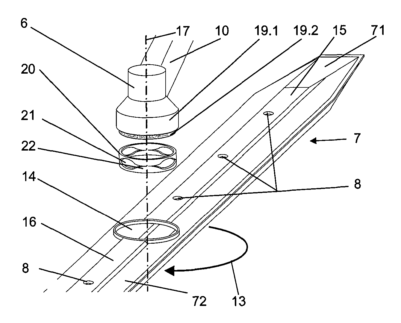
dirt adhering to the dishes is removed more effectively, so that a better cleaning result is achieved despite the fact that water is being saved. Pulsed spray jets act upon the dishes to be cleaned, which leads to a more efficient cleaning operation. Here, the spraying device is supplied by the circulation pump so that, as a result of the changed rotational speed of the circulation pump, the size or the interval of the drops can be quickly changed. Volume flows are created in the spraying device when the circulation pump is operated. These volume flows are employed to bring about functional changes and / or movements in the spraying device. According to the invention, by means of a certain volume flow, a functional element is moved and / or driven from one position into the other. This change in position serves to influence the parameters of the spray jets. Due to the fact that the spray arm is provided with rotating means that cause the spray nozzles to open and close so as to create pulsed spray jets, the jet shape, the jet speed, the jet type, the jet direction, the spray drop interval and the
nozzle position are all influenced. In this context, the means are rotated exclusively by the washing liquid that is circulated in the dishwasher tub by the circulation pump.
[0009] In a first advantageous embodiment, the means are arranged in the area of the axis of rotation of the spraying device and they can be rotated in the plane of the spraying device at a rotational speed that differs from that of the spraying device. This allows for a simple construction and the rotating capacity of the spraying device is not impaired.
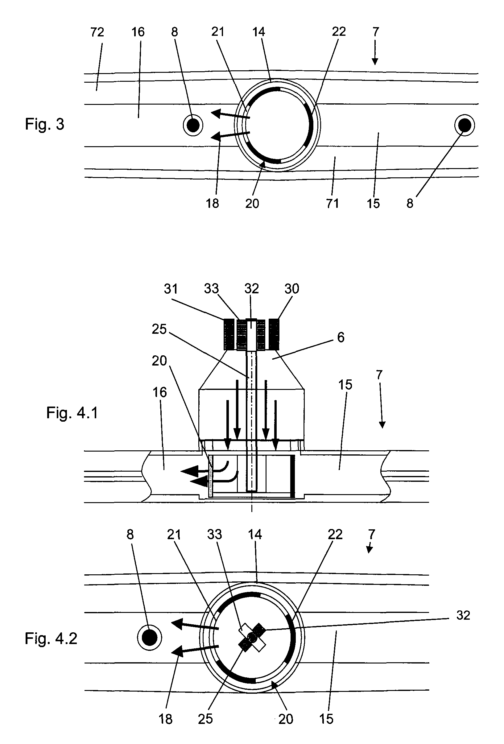
[0011] It is advantageous for the openings in the outer wall of the closing element to be positioned in such a way relative to the channels connected to the spray nozzles that only the path of the washing liquid to some of the channels is interrupted during a relative rotation between the closing element and the spraying device. A simultaneous closing of all of the nozzles would cause the entire circulating liquid
mass to be decelerated, so that the energy of the moved
liquid column and thus its cleaning effect would be reduced. Besides, the
slow rotation of the closing element brought about by this deceleration would increase the
static friction, thus promoting jamming of the element. In a simple manner, the alternating closing and opening in the case of a spray arm having precisely two spray arm halves is achieved by an odd number of closure surfaces. In this context, it is advantageous for the closing element to have three closure surfaces. As a result, the force brought to bear by the pressure of the washing liquid is more uniformly distributed over the individual closure surfaces, thus avoiding tilting of the closing element and
resultant jamming. Moreover, the modulation frequency is raised which, in turn, enhances the cleaning performance.
[0015] The
turbine blades can be situated on a shaft that extends through the center of the closing element or the body. However, it is advantageous to arrange the
turbine blades inside the closing element or the body since then, the space needed to accommodate the element is kept small. Moreover, with this embodiment, the closing element or the body can be mounted, or supported, on one side which, in turn, reduces the complexity of the components. Here, it is advantageous for a stub shaft arranged on the closing element to run through a sliding bearing arranged in the center of the spraying device.

