Sensor chip for laser optical mouse and related laser optical mouse

a laser optical mouse and laser optical mouse technology, applied in the field of laser optical mouse, can solve the problems of inability to judge movement accurately, increase the complexity and cost of such mice, and the installation of the lens

Inactive Publication Date: 2006-12-14
PIXART IMAGING INC
View PDF6 Cites 25 Cited by
  • Summary
  • Abstract
  • Description
  • Claims
  • Application Information

AI Technical Summary

Problems solved by technology

This is the case with the optical mouse 10, and it therefore lacks the capability to judge move...

Method used


Image

  • Sensor chip for laser optical mouse and related laser optical mouse
  • Sensor chip for laser optical mouse and related laser optical mouse
  • Sensor chip for laser optical mouse and related laser optical mouse

Examples


Embodiment Construction

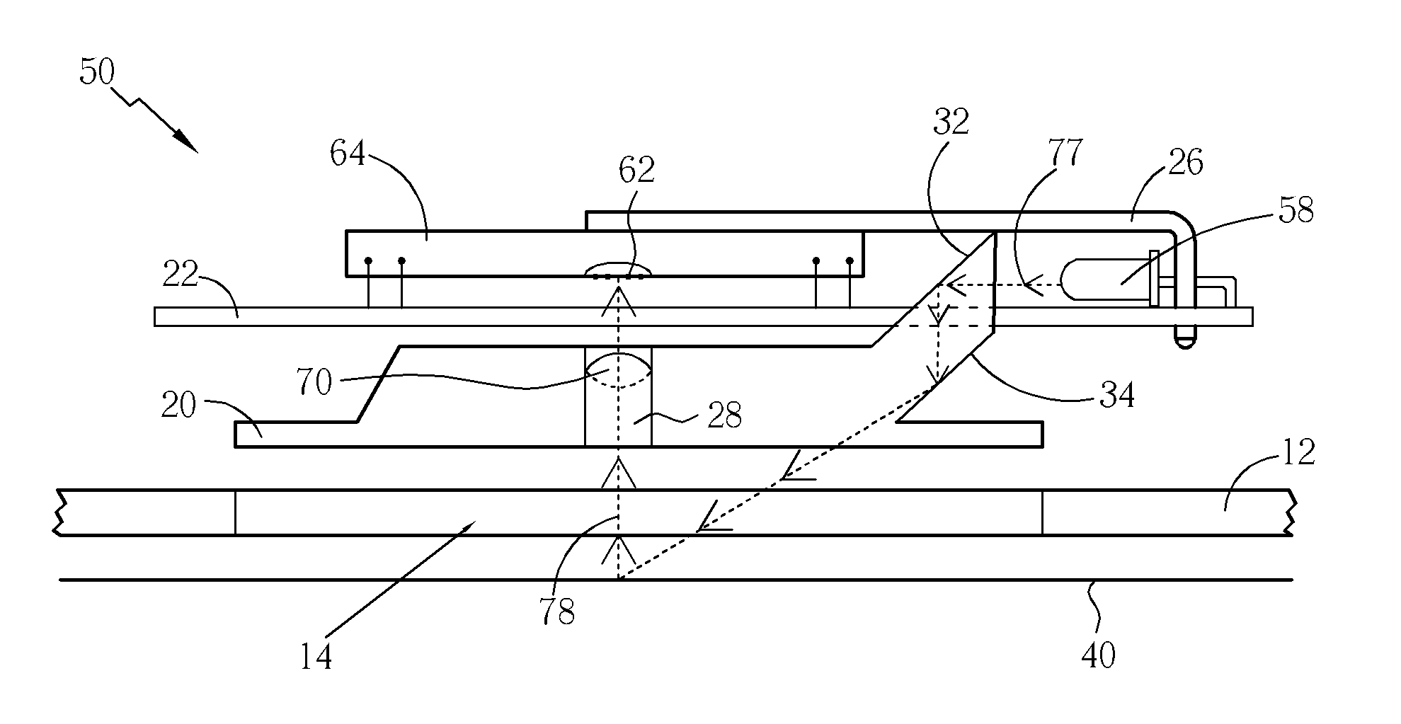
[0022] Please refer to FIG. 4, which is a side view of a laser optical mouse 50 of the preferred embodiment according to the present invention. The laser optical mouse 50, like the optical mouse 10, comprises a bottom surface 12, an opening 14, a light-guiding unit 20, a circuit board 22, a light source chip 26, and an aperture 28, but does not comprise an LED 18 or sensor chip 14. However, laser optical mouse 50 has a laser diode 58 and another sensor chip 64 instead. The sensor chip 64 comprises a plurality of sensor units 62 for sensing light, and a processor (not shown) coupled to the sensor units.

[0023] The laser diode 58 generates coherent light 77. Because the laser diode 58 is opposite the first total reflection surface 32, most of the light 77 will travel to the first total reflection surface 32 and, reflected by the first total reflection surface 32, to the second total reflection surface 34. Reflected by the second total reflection surface 34, the light 77 passes through...


PUM


Abstract

A sensor chip for a laser optical module has a plurality of sensor units and a processor. The sensor units sense speckles formed on a working plane and generate image data. A distance between each of the sensors and a closest sensor is not larger than 30 micrometers. The processor processes the image data and generates a display signal, which corresponds to the movement of the laser optical mouse.

Description

BACKGROUND OF THE INVENTION [0001] 1. Field of the Invention [0002] The present invention relates to a laser optical mouse, and more particularly, to a sensor chip for a laser optical mouse and related laser optical mouse. [0003] 2. Description of the Prior Art [0004] Capable of fulfilling everything from traditional functions, such as document processing and program operation, to modern multimedia, game playing, and other functions, a personal computer (PC) has become an important device in our daily lives. Computer mice and keyboards used for controlling PCs have improved too. For example, sensing techniques that mice use to sense movement have been improved from physical wheels to optical navigation. Also, the controlling capability that mice offer have been improved from simple cursor control to a variety of fascinating functions, such as a zoom-in and zoom-out functions and a fingerprint identification function. With one finger on a mouse, a user of a computer can be in total c...

Claims


Application Information

Patent Timeline
IPC IPC(8): G09G5/08
CPCG06F3/0317G06F3/03543
Inventor LAN, JENG-FENGKUO, MING-HUI
Owner PIXART IMAGING INC
Why Eureka
Try Eureka