Use of overlay diagnostics for enhanced automatic process control

a technology of automatic process control and overlay, applied in the field of overlay measurement techniques, can solve problems such as affecting overlay measurement, affecting overlay measurement, and reporting overlay results that are not reliable,

Inactive Publication Date: 2006-12-14
KLA TENCOR TECH CORP
View PDF1 Cites 19 Cited by
  • Summary
  • Abstract
  • Description
  • Claims
  • Application Information

AI Technical Summary

Problems solved by technology

Unfortunately, the reported overlay results may not be reliable in certain situations.
That is, the measured overlay measurements may be affected by other factors besides misalignment of the target.
The overlay measurement may be affected by background noise associated with the measured target.
In one example, background may cause an overlay error to be measured when the target is not misaligned.
Systematic errors, such as asymmetry may also cause the measured overlay error to be inaccurate.
In another example, a target which has significant asymmetries, combined with a significant true overlay error, may result in zero measured overlay error.
Thus, the asymmetry error may go unnoticed and steps to correct process problems leading to such asymmetry may go uninitiated and adversely affect yield.

Method used


Image

  • Use of overlay diagnostics for enhanced automatic process control
  • Use of overlay diagnostics for enhanced automatic process control
  • Use of overlay diagnostics for enhanced automatic process control

Examples


first embodiment

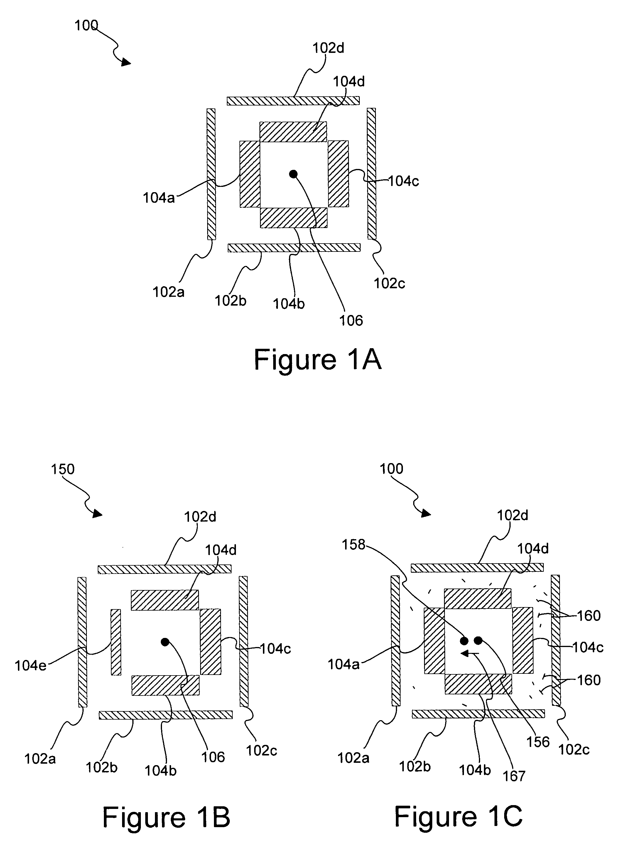
[0051] Any suitable techniques may be used to calculate a confidence level for the target overlay data based on the provided systematic and / or noise metrics. FIG. 5 is a flowchart illustrating a procedure 500 for determining the confidence level of particular overlay data in accordance with the present invention. Initially, a set of calibration wafers are run in operation 502. The weight values for the target diagnostic metric are estimated from the data in operation 504. The data is generally raw overlay and metrics values. The product wafers are then run in operation 506. A total target uncertainty (TTU) is then calculated for the current target in operation 508. TTU is defined as, for example, the target of FIGS. 1A˜1C or FIG. 3BTTU=A*AsymmetryInnerX+AsymmetryInnerY2+B*AsymmetryOuterX+AsymmetryOuterY2+C*(NoiseMetricX)2+(NoiseMetricY)22

where A, B, and C are weights. The units may be any unit of measurement, such as nm.

[0052] After the TTU value is determined, it is then determin...

second embodiment

[0053]FIG. 6 is a flowchart illustrating a procedure 600 for determining a confidence level in accordance with the present invention. The operations 602-606 are similar to the operations 502-506 of FIG. 5. However, in this embodiment a relative target uncertainty (RTU) value is calculated for the current target in operation 608. In this embodiment, the confidence level result is relative to the overlay budget or some other variable, and translated to a relative notation, such as a %. RTU may be defined relative to the TTU value and a Reference Value as: RTU=(1-TTUReferenceValue)*100⁢%

[0054] The Reference Value is generally determined by the overlay budget or some other representative process value. After the RTU value is determined, it is then determined whether the RTU value is less than a predetermined threshold in operation 610. If the RTU is not less than the threshold, the target is good in operation 614. If the RTU is less than the threshold, the target is a flyer in operatio...

fourth embodiment

[0058]FIG. 8 is a flowchart illustrating a procedure 800 for determining a confidence level with the present invention. In general terms, this technique is based on the relative accuracy of the current target metric with respect to calibration data. Calibration wafers (lot, set of lots) are run and means of the metrics are calculated. Then for the current run, the relative accuracy of the metric is calculated. And at the final step, the results are added to the calibration data and means are recalculated.

[0059] Initially, a set of calibration wafers are run in operation 802, and the means of the metrics for the calibration wafers are then calculated in operation 803. The weights are then estimated based on the data in operation 804. A set of product wafers are then run in operation 806. A calibration relative confidence level (CRCL) value is then calculated for the current target in operation 808. The CRCL may be defined as for example, the target of FIGS. 1A˜1C or FIG. 3B as: CRCL...


PUM

PropertyMeasurementUnit
noiseaaaaaaaaaa
lateral displacementaaaaaaaaaa
optical instrumentaaaaaaaaaa

Abstract

Disclosed are apparatus and methods for obtaining and analyzing various unique metrics or “target diagnostics” from one or more semiconductor overlay targets. In one embodiment, an overlay target is measured to obtain one or both of two specific types of target diagnostic information, systematic error metrics and / or random noise metrics. The systematic error metrics generally quantify asymmetries of the overlay target, while the random noise metrics quantify and / or qualify the spatial noise that is proximate to or associated with the overlay target.

Description

CROSS REFERENCE TO RELATED APPLICATIONS [0001] This application is a continuation of U.S. patent application Ser. No. 10 / 438,963 (Attorney Docket No. KLA1P092D1) filed on 14 May 2003, which claims priority of (i) U.S. Provisional Application No. 60 / 386,285 (Attorney Docket No. KLA1P092P), filed on 5 Jun. 2002, (ii) U.S. Provisional Application No. 60 / 395,847 (Attorney Docket No. KLA1P092P2), filed on 11 Jul. 2002, and (iii) U.S. Provisional Patent Application No. 60 / 456,681 (Attorney Docket No. KLA1P092P3) filed on 19 Mar. 2003. These applications are herein incorporated by reference in their entirety for all purposes.BACKGROUND OF THE INVENTION [0002] The present invention relates generally to overlay measurement techniques, which are used in semiconductor manufacturing processes. More specifically, the present invention relates to analyzing overlay marks (also called overlay targets) used for measuring alignment error between different layers or different patterns on the same laye...

Claims


Application Information

Patent Timeline
Patent Type & Authority Applications(United States)
IPC IPC(8): G06K9/00G03F7/20
CPCG03F7/705G03F7/70633G03F7/70516
Inventor SELIGSON, JOEL L.GHINOVKER, MARKROBINSON, JOHNIZIKSON, PAVELADEL, MICHAEL E.SIMKIN, BORISTULIPMAN, DAVIDLEVINSKI, VLADIMIR
Owner KLA TENCOR TECH CORP
Why Eureka
Try Eureka