Bipedal damper turbine blade

a turbine blade and damper technology, applied in the field of turbine rotor blades, can solve the problems of affecting the operation of the turbine blad

Active Publication Date: 2006-12-14
GENERAL ELECTRIC CO
View PDF2 Cites 34 Cited by
  • Summary
  • Abstract
  • Description
  • Claims
  • Application Information

AI Technical Summary

Benefits of technology

[0010] Accordingly, it is desired to provide an improved damper for a gas turbine engine turbine blade.

Problems solved by technology

Each rotor blade is also subject to pressure and thermal loads and stresses from the combustion gases which flow thereover during operation.
And, the blades are also subject to vibratory stress due to the dynamic excitation thereof by the rotating blades and the pressure forces from the combustion gases.
However, these dampers have limited effectiveness for the various modes of vibration of the turbine blade during operation, including the higher order natural modes of airfoil vibration which involve complex combinations of airfoil bending in both the chord and span directions.

Method used


Image

  • Bipedal damper turbine blade
  • Bipedal damper turbine blade
  • Bipedal damper turbine blade

Examples


Embodiment Construction

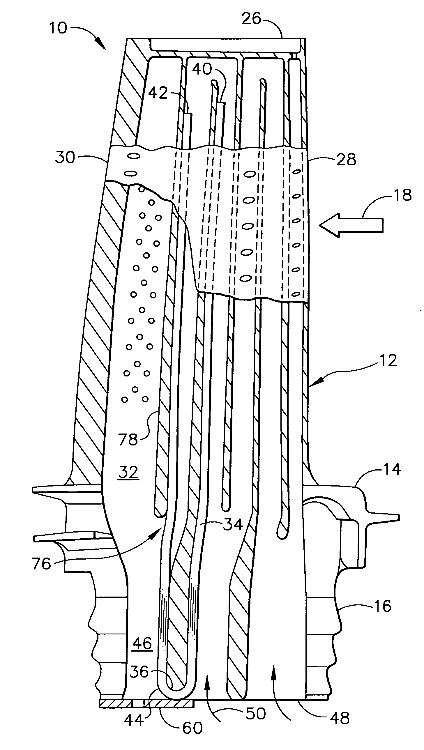
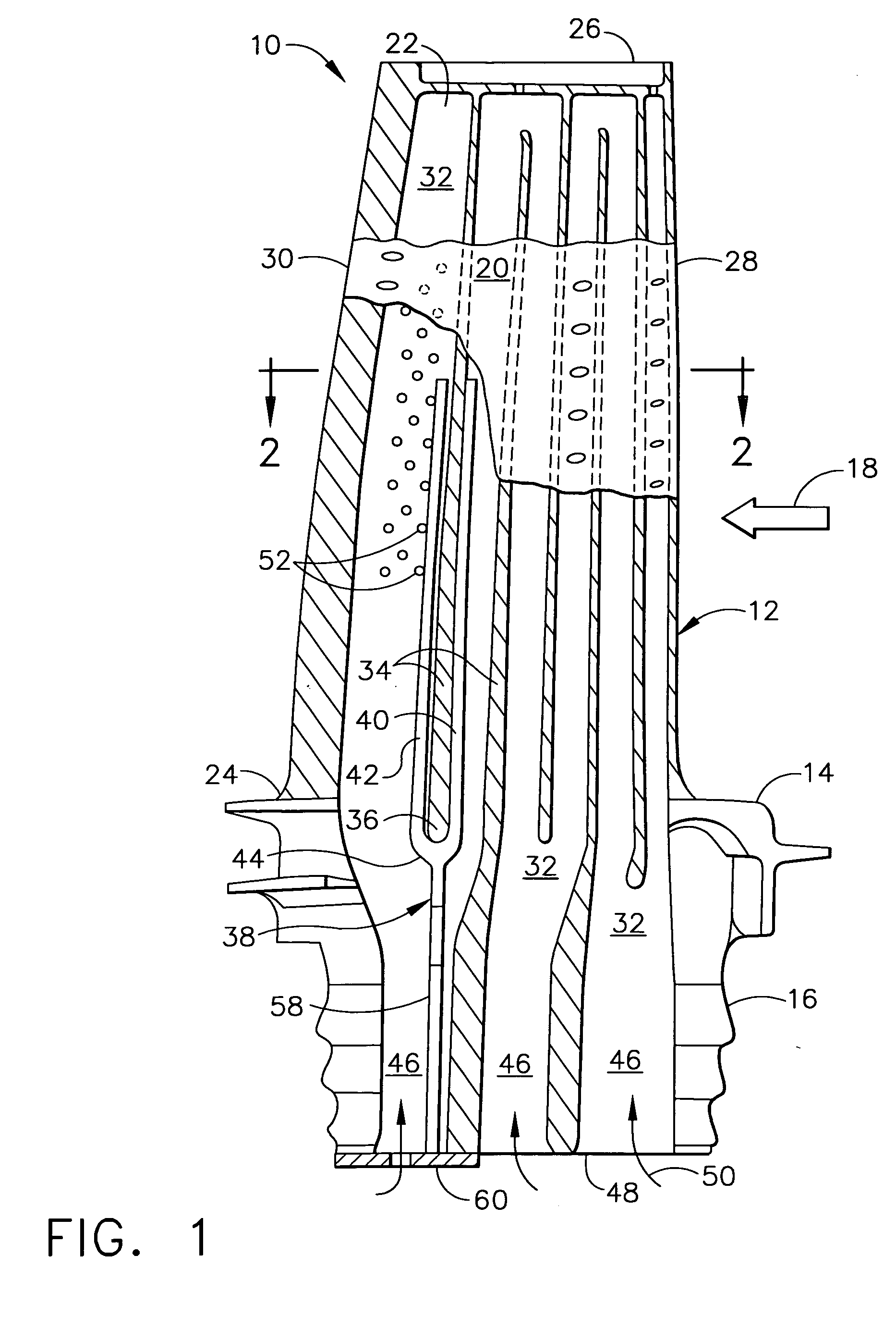
[0021] Illustrated in FIGS. 1 and 2 is an exemplary turbine rotor blade 10 for use in the high pressure turbine of a gas turbine engine. The blade includes a hollow airfoil 12, radially inner platform 14, and a supporting dovetail 16 formed in a unitary or integral cast assembly.

[0022] During operation, the blade is suitably supported in turbine rotor disk (not shown) by the dovetail 16 mounted in a complementary dovetail slot in the perimeter thereof. Combustion gases 18 are generated in a combustor (not shown) and flow over the airfoil 12 which extracts energy therefrom for rotating the supporting rotor disk.

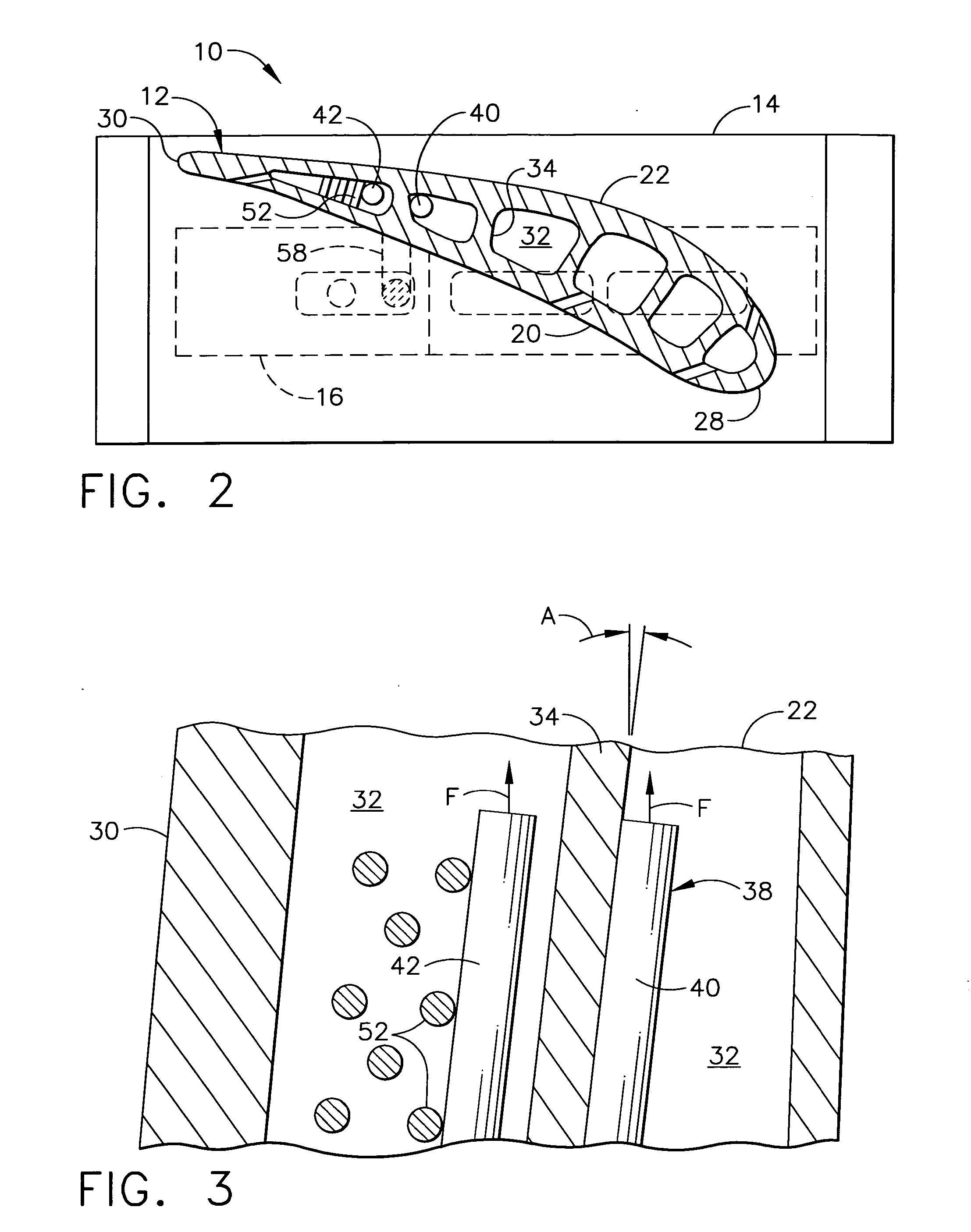
[0023] The airfoil 12 includes a generally concave pressure side 20 and a circumferentially opposite, generally convex suction side 22 extending in radial or longitudinal span between a root 24 at the platform to a radially outer tip 26. The two sides also extend in axial chord between opposite leading and trailing edges 28,30 over the full span of the airfoil between its op...


PUM


Abstract

A turbine blade includes an airfoil, platform, and dovetail. The airfoil includes a plurality of flow channels being separated by partitions. A primary partition includes an inner saddle. And, a bipedal damper includes a pair of legs extending into the flow channels, and integrally joined together at a seat bridging the saddle.

Description

BACKGROUND OF THE INVENTION [0001] The present invention relates generally to gas turbine engines, and, more specifically, to turbine rotor blades therein. [0002] In a gas turbine engine, air is pressurized in a compressor and mixed with fuel in a combustor for generating hot combustion gases. Energy is extracted from the combustion gases by turbine rotor blades which in turn power the compressor, and an upstream fan in an exemplary turbofan aircraft engine application. [0003] Turbine blades typically increase in radial size in the downstream direction as energy is extracted from the combustion gases. And, high pressure turbine blades are typically hollow and provided with internal cooling circuits or channels through which a portion of the pressurized compressor air is channeled for cooling the blades during operation in the environment of the hot combustion gases. [0004] Each rotor blade includes an airfoil extending radially outwardly from an inner platform, with the platform bei...

Claims


Application Information

Patent Timeline
Patent Type & Authority Applications(United States)
IPC IPC(8): F01D5/18
CPCF01D5/187F01D5/26Y02T50/671Y02T50/676F05D2260/96F05D2250/72F05D2250/70F05D2260/202F05D2260/2212F05D2260/22141Y10S416/50F01D5/16Y02T50/60
Inventor BUSBEY, BRUCE CLARKWEAVER, MATTHEW MARKGARAY, GREGORY TERRENCE
Owner GENERAL ELECTRIC CO
Why Eureka
Try Eureka