
Damper system for heater stack

a technology for heater stacks and dampers, which is applied in the direction of damper arrangement, combustion process, lighting and heating apparatus, etc., can solve the problems of inability to properly control the draft the inability of current stack dampers to control the draft, and the inability to control the draft properly. , to achieve the effect of improving the damper and draft control, improving the thermal efficiency of fired heaters

Active Publication Date: 2017-07-13
GARG ASHUTOSH
View PDF18 Cites 12 Cited by
  • Summary
  • Abstract
  • Description
  • Claims
  • Application Information

AI Technical Summary

Benefits of technology

The aim of this patent is to enhance the thermal efficiency of fired heaters.

Problems solved by technology

While most of the plant operators are aware of the importance of controlling excess oxygen in the fired heaters, draft control in fired heaters is often overlooked.
This type of operation causes considerable loss of energy.
Current stack dampers are not capable of controlling draft properly and do not work reliably.
Even the pneumatically operated dampers are not designed correctly to control the draft, especially when the heater is operating at reduced conditions.
The operators are scared to close the dampers and reduce the excess draft in the heater.

Method used


Image

  • Damper system for heater stack
  • Damper system for heater stack
  • Damper system for heater stack

Examples


Embodiment Construction

[0017]The invention is described with reference to cabin heaters, but it applies to all other types of heaters that employ a stack with damper as well, for example, vertical cylindrical, box, arbor, and fired heaters that use induced draft fans as well. It also applies to heaters having long convection sections or multiple convection section with off take ducts that connect the convection sections to the stack.

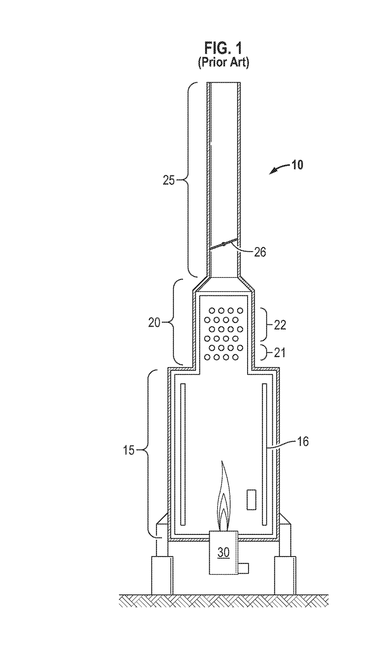
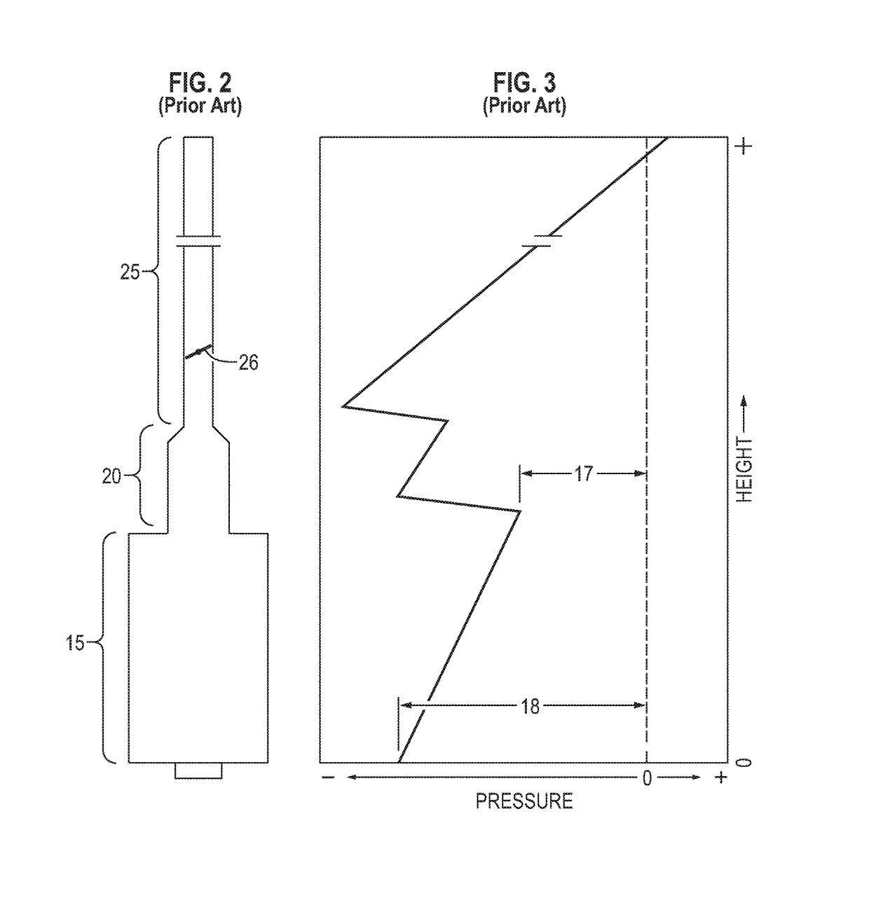
[0018]A typical fired heater 10 according to the prior art is shown cross-sectionally in FIG. 1. The heater consists of three major components: a radiant section 15, a convection section 20 and a stack 25. Radiant section 15 contains fired tubes 16. Convection section 20 contains guard tubes 21 and finned tubes 22. The fired heater is fired using oil or gas as a fuel. The fluid carried in the tubes absorbs the heat mostly by radiant heat transfer and convective heat transfer from the flue gases. The flue gases are vented to the atmosphere through the stack. Draft is controlled...


PUM


Abstract

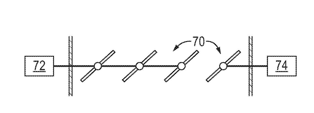
In a stack leading from a fired heater, a plurality of damper blades are positioned at a longitudinal location, each blade being at least partly rotatable around its longitudinal axis to regulate flow through the stack. A plurality of controllers is operatively associated with the plurality of parallel blades to effect rotation of the blades. At least one of the controllers is decoupled from the rest of the plurality of controllers and used to independently control at least one but not all of the plurality of damper blades. The damper blades can be parallel or opposed.

Description

FIELD OF THE INVENTION[0001]The invention relates to dampers for heater stacks and using the dampers to control draft and improve efficiency.BACKGROUND OF THE INVENTION[0002]Petroleum refining is the most energy intensive industry in the USA and accounts for 7.5% of the total energy consumption in the country. Total energy costs are on the order of $20 billion dollars per year, although a large portion of the required energy is produced internally. The situation is very similar in the petrochemical and fertilizer Industry.[0003]Fired heaters are major consumers of energy in the refining and petrochemical industries. Almost 40 to 70% of the total energy consumption in a refinery or petrochemical plants is in fired heaters. While most of the heaters are designed for a thermal efficiency of 70-90%, the actual operating efficiencies are much lower.[0004]While most of the plant operators are aware of the importance of controlling excess oxygen in the fired heaters, draft control in fired...

Claims


Application Information

Patent Timeline
Patent Type & Authority Applications(United States)
IPC IPC(8): F23L13/02F23L17/00
CPCF23L17/00F23L13/02
Inventor GARG, ASHUTOSH
Owner GARG ASHUTOSH
Learn More