Jet generator and electronic device

a technology of electronic devices and generators, applied in the field of jet generators, can solve the problems of undetectable vibration of the diaphragm through, and achieve the effect of not decreasing the amount of gas ejected or cooling capability

Inactive Publication Date: 2006-12-14
SONY CORP
View PDF17 Cites 60 Cited by
  • Summary
  • Abstract
  • Description
  • Claims
  • Application Information

AI Technical Summary

Benefits of technology

[0009] This problem arises from a vibrational force produced by the reciprocating motion of the diaphragm, which has weight, and an actuator that actuates the diaphragm. The transmission of vibration can be reduced by, for example, decreasing the weight or amplitude of vibration of the diaphragm or the frequency used. However, there are trade-offs between the reduction in the weight of the diaphragm and the maintenance of the strength thereof and between the reduction in amplitude of vibration and frequency and the increase in the amount of air ejected for increased cooling efficiency (the amount of air ejected is proportional to the product of the amplitude of vibration, the effective cross-sectional area, and the frequency).
[0010] Accordingly, it is desirable to provide a jet generator that can inhibit the transmission of vibration to the outside thereof without decreasing the amount of gas ejected or cooling capability and also provide an electronic device including the jet generator.
[0012] This jet generator can inhibit the transmission of vibration to the outside of the casing or the jet generator because the vibrators vibrate with the vibrational forces thereof being synthesized so as to attenuate each other. In addition, the jet generator can avoid a decrease in the amount of gas ejected, or rather can increase it, because the vibrational forces attenuate each other even for increased amplitudes of vibration.
[0016] The actuators may actuate the vibrators with, for example, an electromagnetic effect, a piezoelectric effect, or an electrostatic effect.
[0026] In this embodiment, the casings may have engaging portions that engage with each other. These engaging portions allow the casings to be stacked on top of each other or to be arranged in a plane according to the shapes and positions of objects of interest, such as heat sources, to achieve, for example, effective heat dissipation.
[0030] The jet generators and the electronic devices according to the embodiments described above can inhibit the transmission of vibration to the outside of the jet generators without decreasing the amount of gas ejected or cooling capability.

Problems solved by technology

If the amplitude of vibration is increased, however, the vibration of the diaphragm is undesirably transmitted through, for example, a casing of a jet generator and a casing of an electronic device including the jet generator.
This problem arises from a vibrational force produced by the reciprocating motion of the diaphragm, which has weight, and an actuator that actuates the diaphragm.

Method used


Image

  • Jet generator and electronic device
  • Jet generator and electronic device
  • Jet generator and electronic device

Examples


Embodiment Construction

[0056] Embodiments of the present invention will now be described with reference to the drawings.

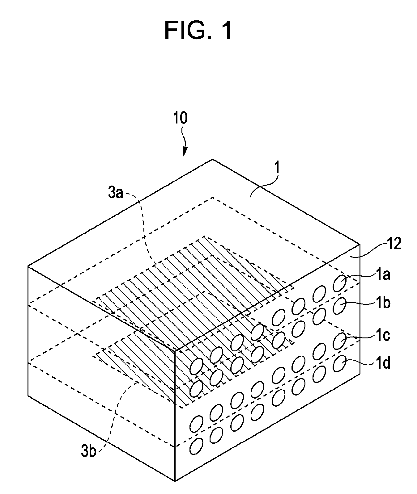
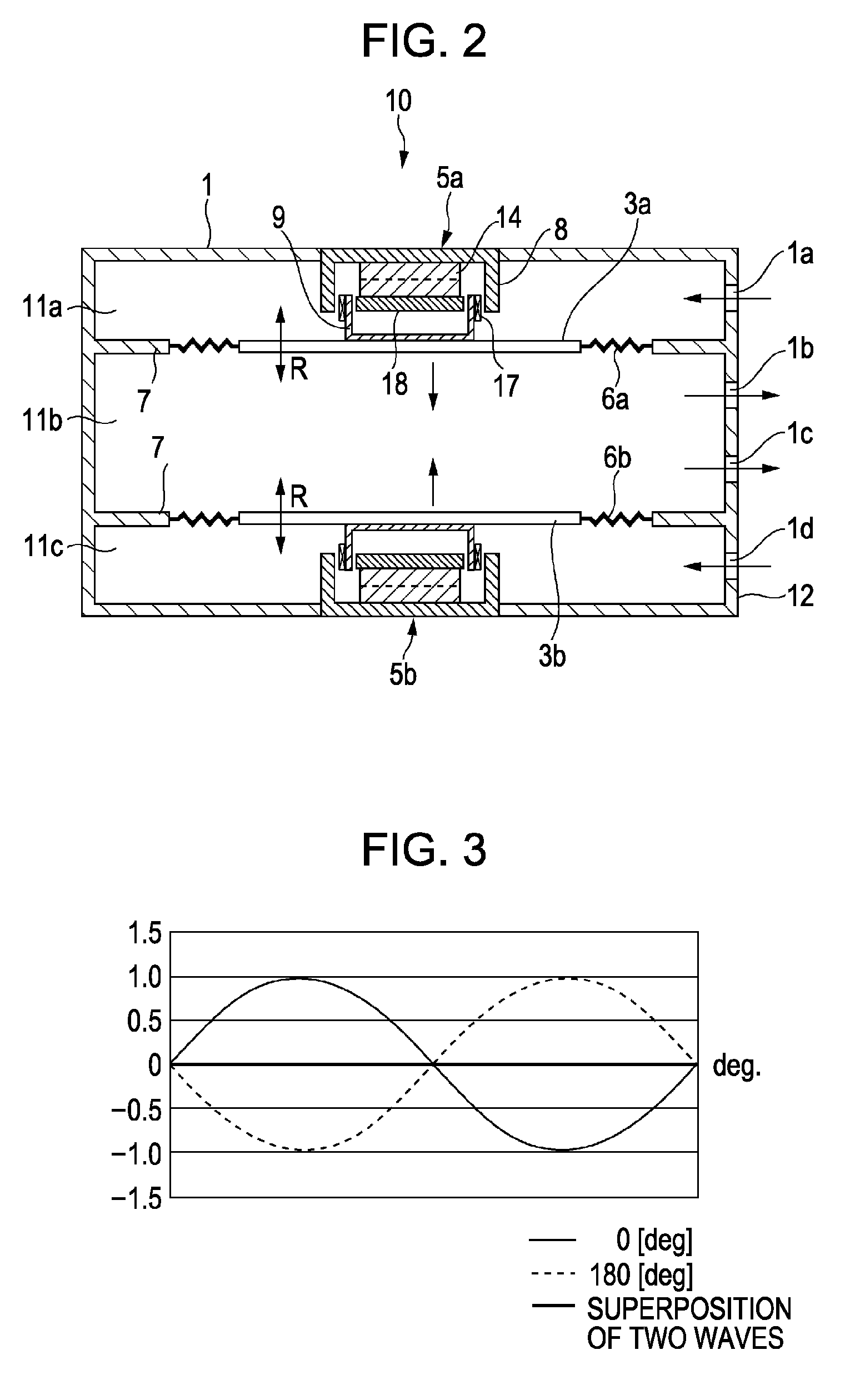
[0057]FIG. 1 is a perspective view of a jet generator according to an embodiment of the present invention. FIG. 2 is a sectional view of the jet generator.

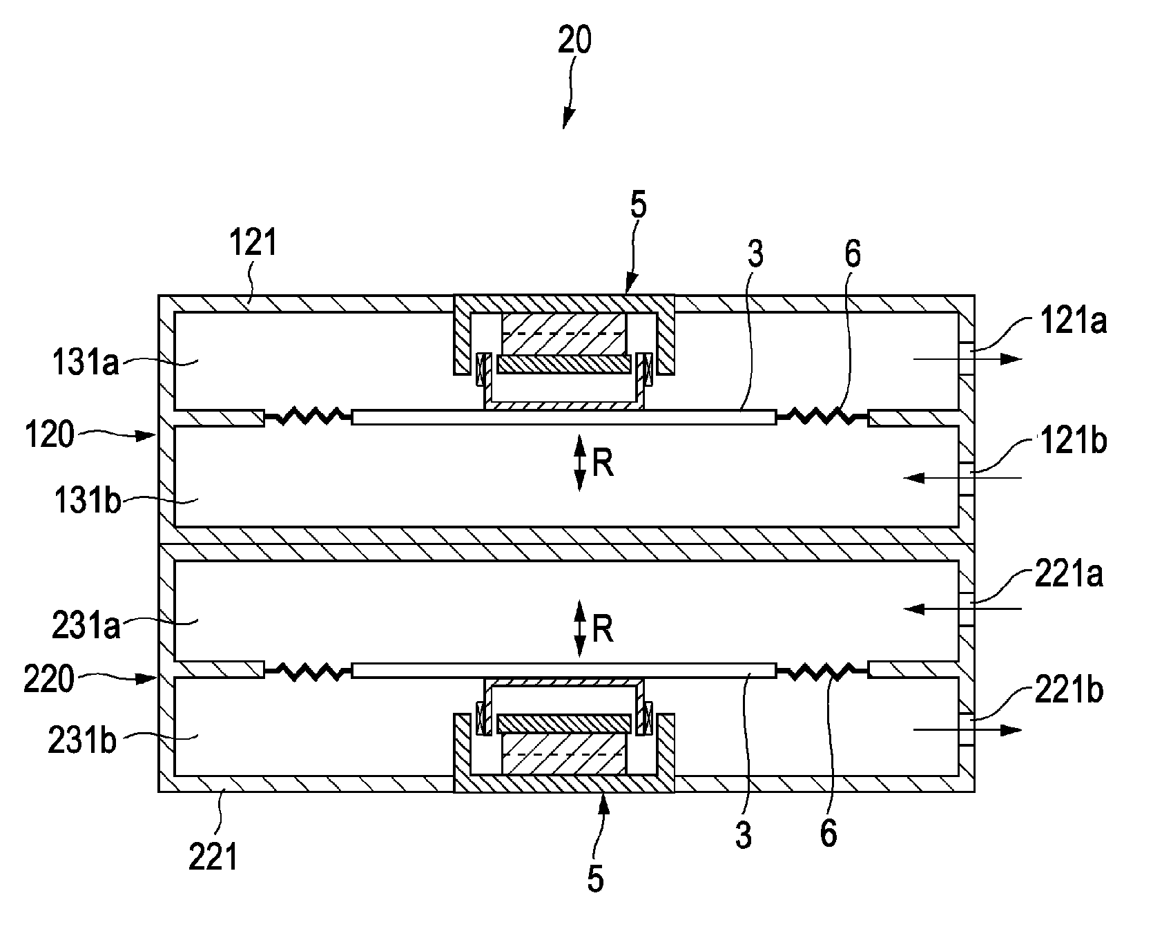
[0058] A jet generator 10 includes a casing 1 containing air. This casing 1 has, for example, a rectangular parallelepiped shape. The casing 1 includes, for example, two opposing diaphragms 3a and 3b and actuators 5a and 5b for actuating the diaphragms 3a and 3b, respectively. For example, the actuator 5a is disposed on the top side of the casing 1, and the actuator 5b is disposed on the bottom side of the casing 1. Elastic supports 6a and 6b are attached to the peripheries of the diaphragms 3a and 3b, respectively. The elastic supports 6a and 6b are also attached to ribs 7 protruding from the inner walls of the casing 1. That is, the diaphragms 3a and 3b are attached to the elastic supports 6a and 6b so as to be vibratable with resp...


PUM


Abstract

A jet generator includes a casing containing a gas and having an opening, vibrators attached to the casing, and actuators for actuating the vibrators. The vibrators vibrate with the vibrational forces thereof being synthesized so as to attenuate each other, thereby vibrating the gas to eject a pulsating jet thereof through the opening.

Description

CROSS REFERENCES TO RELATED APPLICATIONS [0001] The present invention contains subject matter related to Japanese Patent Application JP 2005-134302 filed in the Japanese Patent Office on May 2, 2005, the entire contents of which are incorporated herein by reference. BACKGROUND OF THE INVENTION [0002] 1. Field of the Invention [0003] The present invention relates to jet generators for generating gas jets and electronic devices including the jet generators. [0004] 2. Description of the Related Art [0005] Increased performance of personal computers (PCs) has posed the problem of increased amounts of heat generated from heat sources such as integrated circuits (ICs). Accordingly, a wide variety of heat dissipation techniques have been proposed or commercialized. For example, radiation fins formed of a metal such as aluminum are brought into contact with an IC to transmit heat from the IC to the fins and dissipate it. In addition, a fan is used to forcibly eject warm air in a PC casing a...

Claims


Application Information

Patent Timeline
Patent Type & Authority Applications(United States)
IPC IPC(8): H05K5/00
CPCG06F1/203
Inventor YOKOMIZO, KANJIISHIKAWA, HIROICHIMAKINO, TAKUYANAKAYAMA, NORIKAZUMUKASA, TOMOHARU
Owner SONY CORP
Why Eureka
Try Eureka