Sensor network system, method for data processing of a sensor network system

a sensor network and sensor technology, applied in the field method for data processing of sensor network system, can solve the problems of large program on the node, difficult to change the operation flow, and inability to transmit through radio communication, so as to reduce the number of events to be distributed, reduce the load concentration of the server, and reduce the power consumption of each node.

Inactive Publication Date: 2006-12-14
HITACHI LTD
View PDF8 Cites 109 Cited by
  • Summary
  • Abstract
  • Description
  • Claims
  • Application Information

AI Technical Summary

Benefits of technology

[0014] Further, this invention enables dynamic changing of the operation flow of distributed event handling corresponding to a dynamically changed situation. Thus, as compared with the case of executing the prefixed event handling, it is not necessary to execute useles

Problems solved by technology

A size of the program on the node is enormous, so transmission may be impossible through radio communication.
However, the changing of the operation flow of each node necessitates re-registration of programs of many nodes as in the case of the conventional examp

Method used


Image

  • Sensor network system, method for data processing of a sensor network system
  • Sensor network system, method for data processing of a sensor network system
  • Sensor network system, method for data processing of a sensor network system

Examples


second embodiment

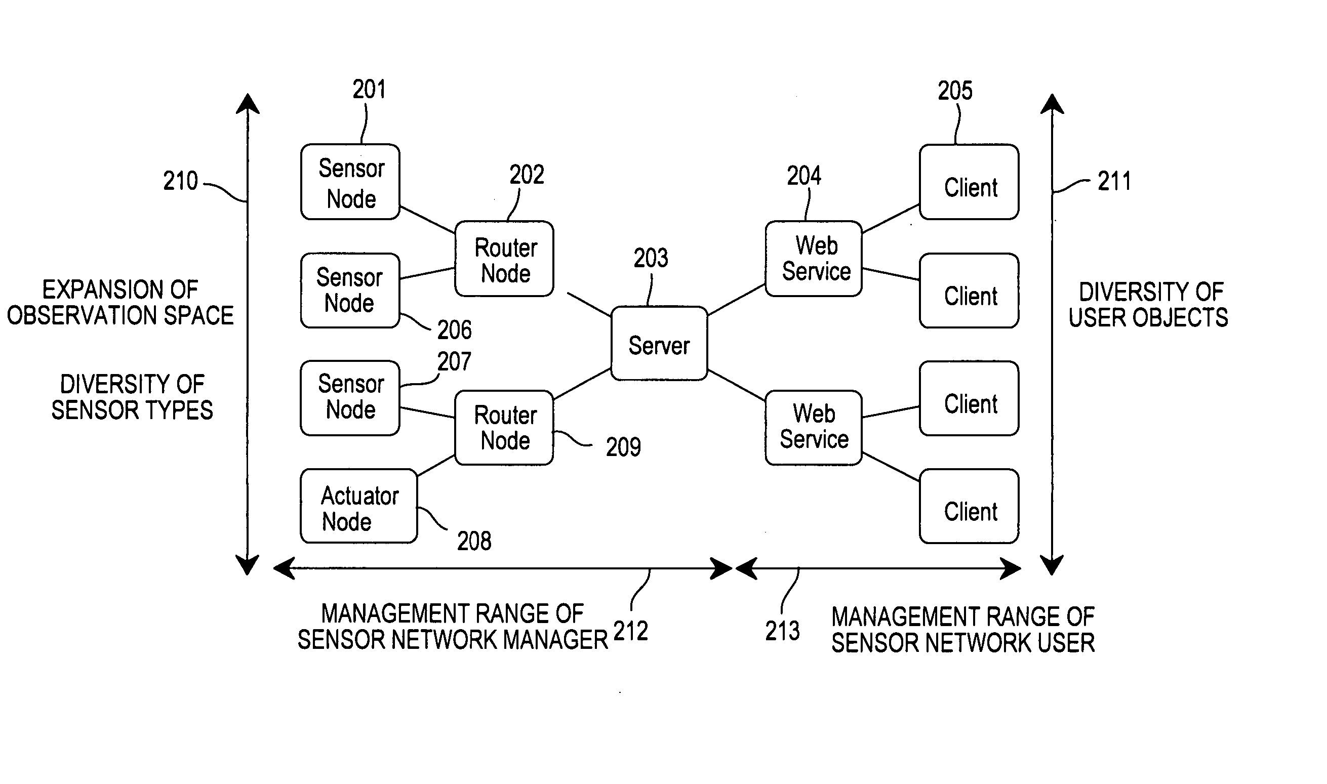
[0299]FIG. 25 shows a sensor network which includes a plurality of clients having different objects according to a

[0300] Referring to FIG. 25, the sensor network including a sensor node 2601, a server 2607, and clients 2614 and 2615 having different objects is presumed. By requests from the clients 2614 and 2615, different events are processed by an event handler 2602 on the sensor node 2601 to issue two types of secondary events 2605. Other components are similar to those of the first embodiment, the sensor nodes 2601 and 2607 are similar to those of the first embodiment sown in FIG. 4, ands the server 2607 is similar to the server 203.

[0301] Now, a “secondary event identifier problem” which has been a problem of the conventional sensor network and its solution will be described.

[0302] Generally, the event 2605 includes an identifier for identifying a type of an event, and an event parameter. In this case, a problem as to who decides the identifier for identifying the type of an ...

first embodiment

[0303] According to this invention, as shown in FIG. 3 of the first embodiment, the secondary event is replaced by the action completion event 116 which is a return of the asynchronous action, and an event return destination is decided by the action ID 113 and the command ID 114. Accordingly, the secondary event identifier problem will not occur.

[0304] Referring to FIG. 25, an “event leakage problem” that has been a problem of the conventional sensor network and its solution will be described.

[0305] A secondary event 2605 output as a result of information processing at the event handler 2602 of the sensor node 2601 is valuable information created corresponding to a user request, and it should not be leaked to other users having opposite advantages. When the event 2605 is bugged on a communication route, there is a possibility of leakage of an event type and an event return destination.

[0306] According to this invention, as shown in FIG. 3, the action completion event 116 does not ...

third embodiment

[0308]FIGS. 26 and 27 shows an example where one client handles a plurality of sensor nodes by a plurality of rules according to a

[0309] Referring to FIG. 26, a sensor network includes a human detection sensor node 2701 for issuing a “human detection event”, a temperature sensor node 2702 for issuing a “temperature observation event”, and a server 2703 having an event handler 2704 mounted thereon to receive those events. Other components are similar to those of the first embodiment. The sensor nodes 2701 and 2702 are similar to the sensor node 201 of the first embodiment, and the server 2703 is similar to the server 203 of the first embodiment.

[0310] Consideration will be given to a case of mounting the following rules in the event handler 2704 of the server 2703. [0311] [Rule 31] An air conditioner is started when a room in which a human is present is at 30° C. or more. [0312] [Rule 32] When a room temperature is 40° C. or more, fire is determined to issue an evacuation order if t...


PUM


Abstract

An operation flow of each node is dynamically changed according to a user request or a situation. A client (205) includes: a step (415) of extracting a script for a lower node from scripts in which processing is preset for a plurality of nodes to distribute the script extracted to the lower node; a step of executing processing for a self node from the script; a step of causing the lower node to receive the script distributed to execute processing for the node; and a step 410 of causing the lower node to extract a script for a node lower than the self node from the scripts, and to distribute the extracted script to the lower node if the script for the lower node is present. Based on a script executed by each node, an event from a lowest sensor node is sent through an intermediate node to the client 205.

Description

CLAIM OF PRIORITY [0001] The present application claims priority from Japanese application P2005-169323 filed on Jun. 9, 2005, the content of which is hereby incorporated by reference into this application. BACKGROUND OF THE INVENTION [0002] This invention relates to a technology of using pieces of information from many sensors connected to a network, and more particularly to a sensor network system used for collecting pieces of information from many regionally distributed sensors to assist decision making as to understanding of a current situation, discovery of abnormality, prediction, and optimization. [0003] There has recently made a progress in development of a sensor network technology of obtaining sensing data from many sensor nodes through a network. The sensor network technology enables use of information obtained by a sensor at a remote place through the network, and must deal with wide and diverse environment observations. In the case of making wide and diverse observation...

Claims


Application Information

Patent Timeline
IPC IPC(8): G06F15/16
CPCH04L67/34H04L67/10H04L67/12H04W40/04H04W84/18
Inventor MURO, KEIRO
Owner HITACHI LTD
Why Eureka
Try Eureka