

Receiving apparatus and method
a technology of receiving apparatus and receiving method, which is applied in the field of receiving apparatus and method, can solve the problem that neither of these layout setups are possibl
- Summary
- Abstract
- Description
- Claims
- Application Information
AI Technical Summary
Benefits of technology
Problems solved by technology
Method used
Image

Examples
first embodiment
[Arrangement]
[0194] A TV broadcast receiving apparatus according to the first embodiment of the present invention will be described below with reference to the accompanying drawings. FIG. 19 is a block diagram showing the arrangement of a TV broadcast receiving apparatus of the first embodiment.
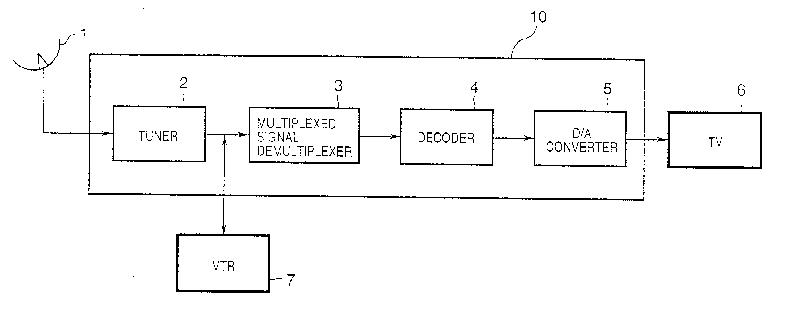
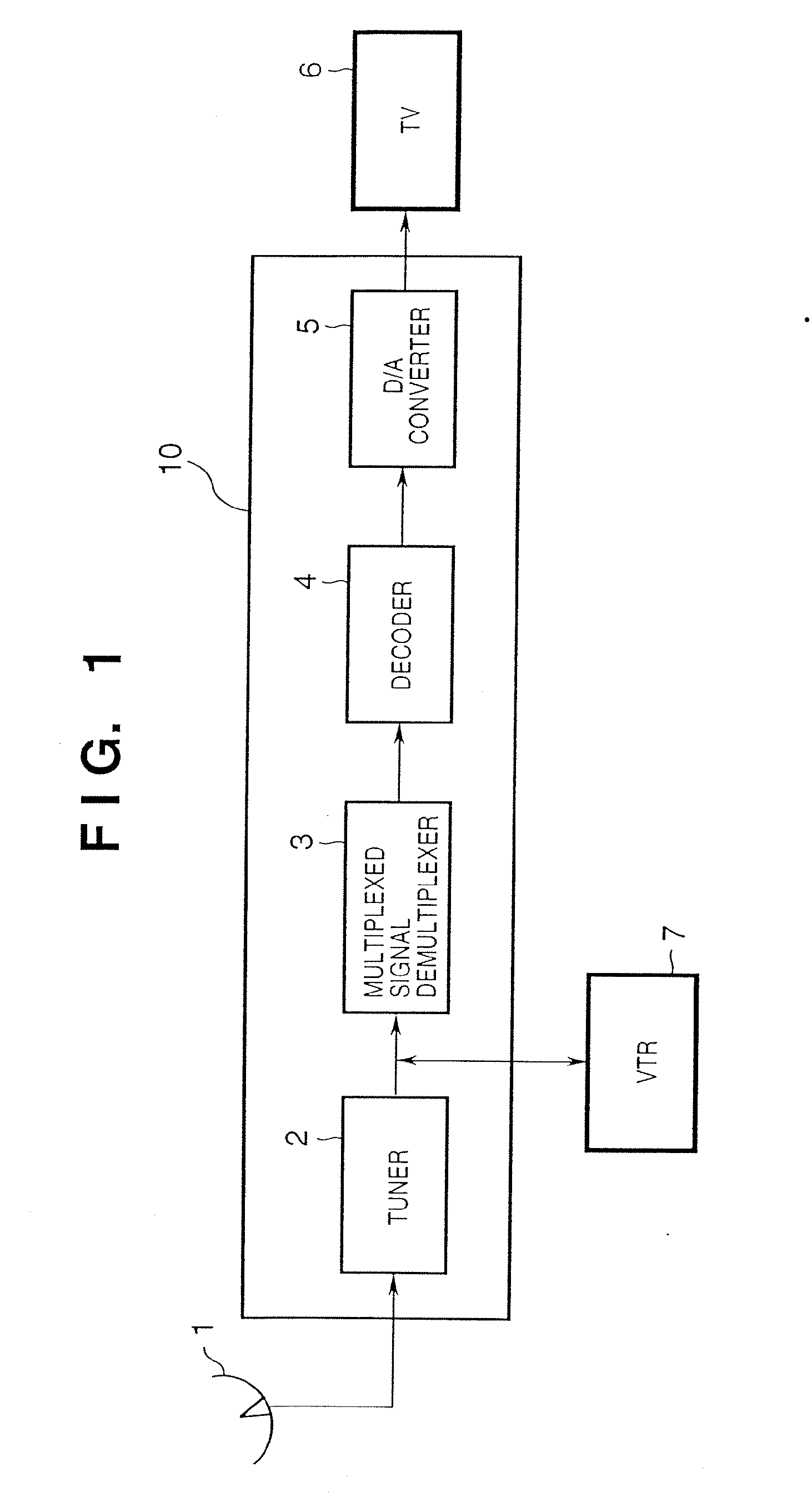
[0195] A digital TV broadcast signal is tuned in and received depending on its broadcast pattern, e.g., by a satellite antenna 21 and tuner 23 in case of satellite broadcast or by a tuner 24 via a cable 22 in case of cable broadcast. TV information received from satellite or cable broadcast is input to a data selector 43 to select one data sequence. The selected data sequence is demodulated by a demodulation circuit 25, and the demodulated data undergoes error correction in an error correction circuit 26.
[0196] Subsequently, the TV information is demultiplexed by a multiplexed signal demultiplexing circuit 27 into image data, sound data, and other system data (additional data). Of these da...
second embodiment
[0230] A TV broadcast receiving apparatus according to the second embodiment of the present invention will be described below. Note that the same reference numerals in the second embodiment denote the same parts as those in the first embodiment, and a detailed description thereof will be omitted.
[0231] In TV broadcast that uses an image encoded by a coding scheme other than MPEG 4 as one MPEG 4 object, the second embodiment makes video display of a TV program with high degree of freedom in layout using a layout (movement, upscaling / downscaling, and the like of an object) set by the user.
[0232] A case will be exemplified below wherein MPEG 2 is used as a photo image coding scheme. That is, a TV broadcast receiving apparatus which receives and displays an image encoded by MPEG 2 (to be also referred to as an “MPEG 2 image” hereinafter) multiplexed on an MPEG 4 bitstream will be explained below. Note that the layout setting method in the second embodiment is the same as that describe...
third embodiment
[Arrangement]
[0251] A TV broadcast receiving apparatus according to the third embodiment of the present invention will be described in detail below with reference to the accompanying drawings. FIG. 30 is a block diagram showing the arrangement of a TV broadcast receiving apparatus of the third embodiment Note that the same reference numerals in the third embodiment denote the same parts as those in the first embodiment, and a detailed description thereof will be omitted.
[0252] In the third embodiment as well, system data (including scene description data and additional data) is decoded by the system data decoding circuit 36. A category information detector 137 detects category information appended to a program from the decoded system data. The detected category information is input to the system controller 38, which generates commands in layout setups with reference to this information. Also, of the decoded system data, data that pertains to scene description is input to the scene...
PUM
 Abstract
Description
Claims
Application Information