Slide fastener
a slide fastener and bottom end technology, which is applied in the direction of slide fasteners, press-button fasteners, snap fasteners, etc., can solve the problems of poor appearance of slide fasteners, and achieve excellent operation and
- Summary
- Abstract
- Description
- Claims
- Application Information
AI Technical Summary
Benefits of technology
Problems solved by technology
Method used
Image
Examples
first embodiment
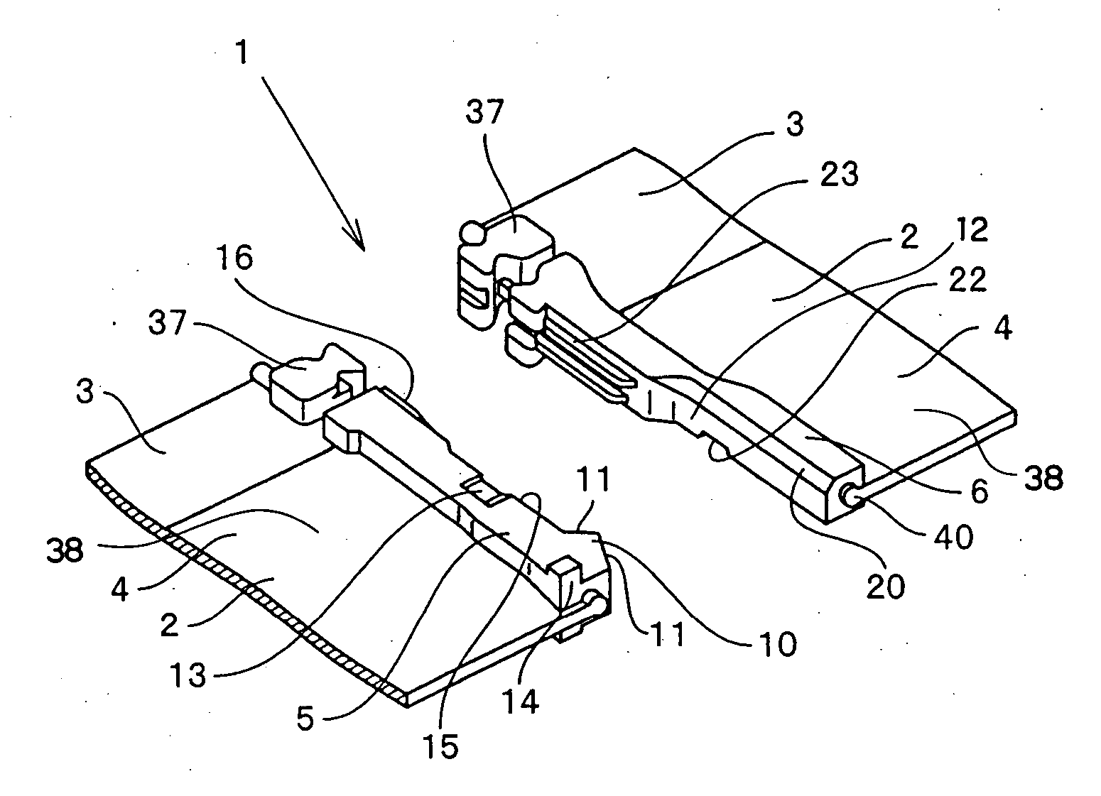
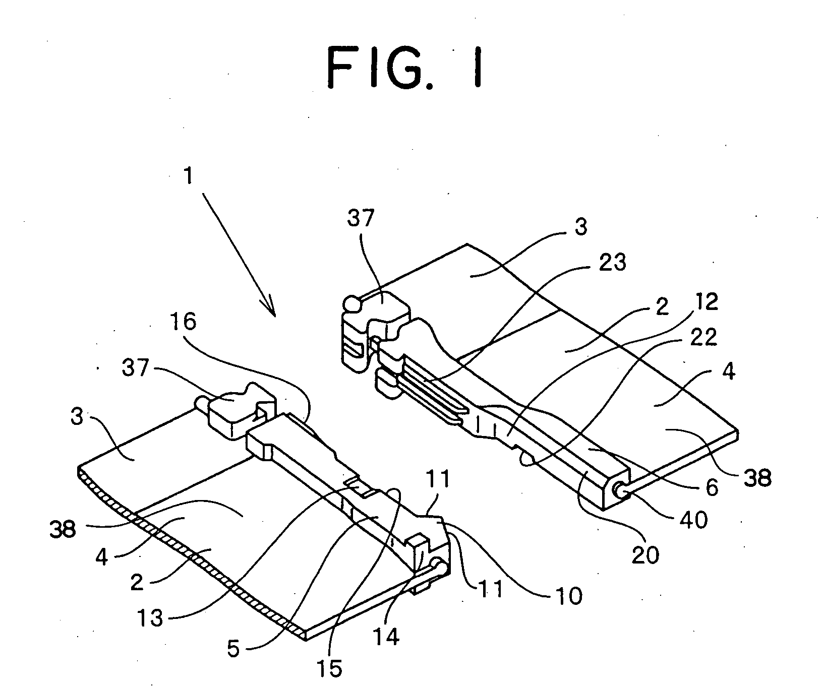
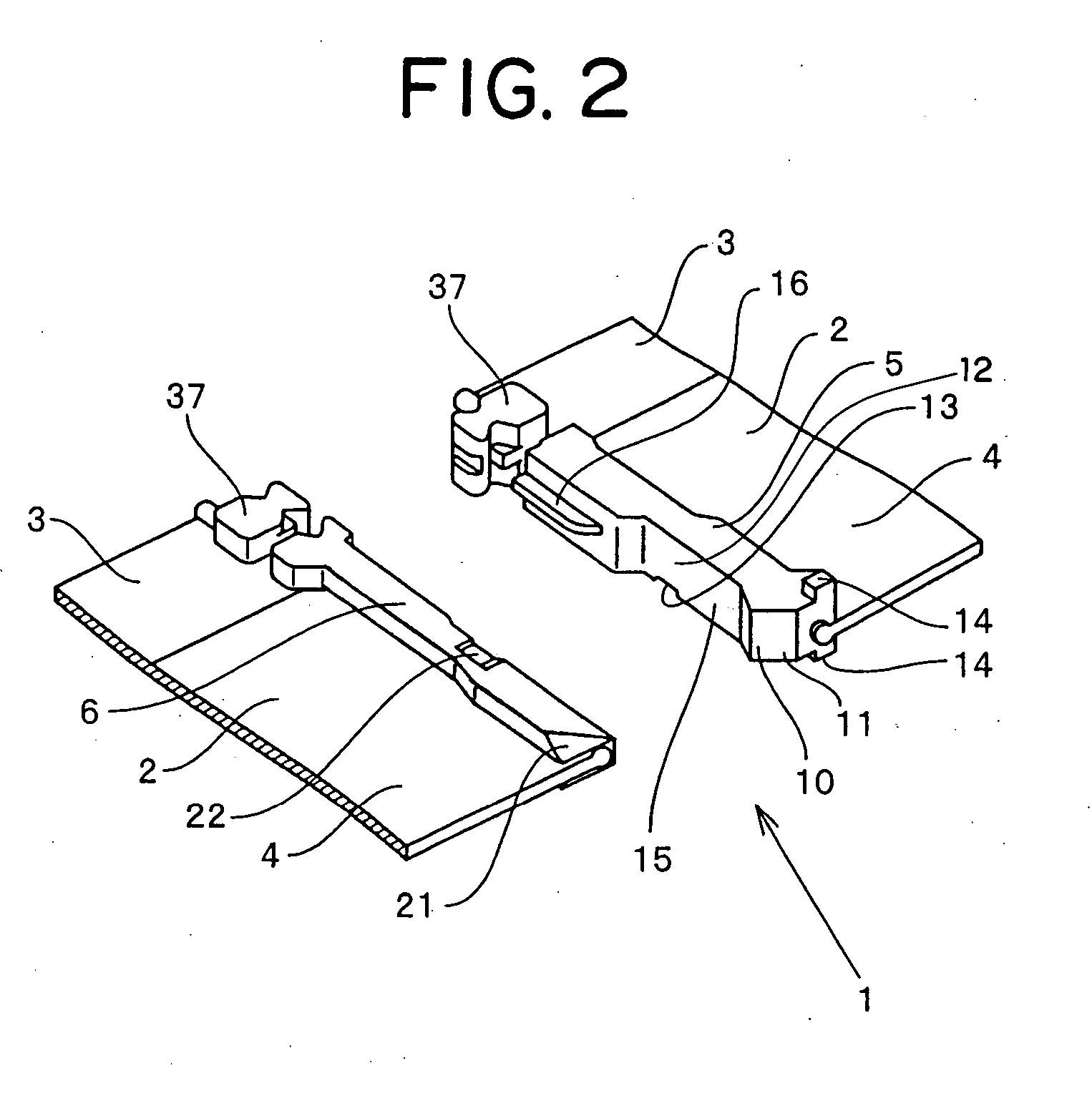
[0040] A separable bottom end stop for a slide fastener according to the present invention will be described. In a separable bottom end stop for a slide fastener according to a first embodiment shown in FIGS. 1 to 7, fastener elements 37 in a single unit are mounted on swollen core threads 40 with respect to fastener tapes 3, the core threads being fixed on side edges of the fastener tapes 3 constituting fastener stringers 2 in a fastener chain 1, by injection molding means using thermoplastic resin such as polyamide, polyacetal, polypropylene, and polybutylene terephthalate. Then, space portions are formed by removing the fastener elements 37 in a specified interval from the fastener chain 1 equipped with the fastener elements 37, and reinforcement tapes are bonded to the space portions by using a resin film such as polyamide and polyacetal. Consequently, a substantially rectangular box pin 5 is formed on the reinforcement tape on one fastener stringer 2 by injection molding using ...
second embodiment
[0049] A separable bottom end stop for a slide fastener according to a second embodiment shown in FIG. 8 shows a modification of the box pin 5 mounted on the fastener stringer 2. As for the configuration of the box pin 5, the box pin 5 mounted on the core thread 40 of the fastener tape 3 with resin by injection molding is substantially rectangular, and the projecting opposite portion 16 capable of engaging the projecting and recessed rows 23 provided on the insert pin 6 is provided on the opposing face 12 to the insert pin 6 of the box pin 5 on the upper side of the box pin 5. The protrusion 10 projecting triangularly is provided on the opposing face 12 at the bottom end portion of the box pin 5, and the projecting portions 14 are provided on the corner portions of both front and rear faces and the recess 13 capable of accommodating the locking pawl 30 of the automatic locking mechanism is provided. The box pin 5 of this embodiment is different from the box pin 5 of the previous emb...
PUM
 Abstract
Description
Claims
Application Information
 - R&D
- Intellectual Property
- Life Sciences
- Materials
- Tech Scout
- Unparalleled Data Quality
- Higher Quality Content
- 60% Fewer Hallucinations
Browse by: Latest US Patents, China's latest patents, Technical Efficacy Thesaurus, Application Domain, Technology Topic, Popular Technical Reports.
© 2025 PatSnap. All rights reserved.Legal|Privacy policy|Modern Slavery Act Transparency Statement|Sitemap|About US| Contact US: help@patsnap.com


