Method of manufacturing stator of rotary electric machine

a technology of rotary electric machines and stator windings, which is applied in the manufacture of dynamo-electric machines, dynamo-electric machines, magnetic bodies, etc., can solve problems such as damage to insulation films covering stator windings

Inactive Publication Date: 2006-12-21
DENSO CORP
View PDF9 Cites 22 Cited by
  • Summary
  • Abstract
  • Description
  • Claims
  • Application Information

AI Technical Summary

Benefits of technology

[0007] The present invention has been made in view of the above-mentioned problem, and an object of the present invention is to provide an improved method of manufacturing a stator of a rotary electric machine, in which insulation films of stator windings are prevented from being damaged.

Problems solved by technology

In this method, however, there is a problem that end portions of the teeth move in the circumferential direction in the bending process, thereby damaging insulation films covering the stator windings disposed in the slots.

Method used


Image

  • Method of manufacturing stator of rotary electric machine
  • Method of manufacturing stator of rotary electric machine
  • Method of manufacturing stator of rotary electric machine

Examples


Embodiment Construction

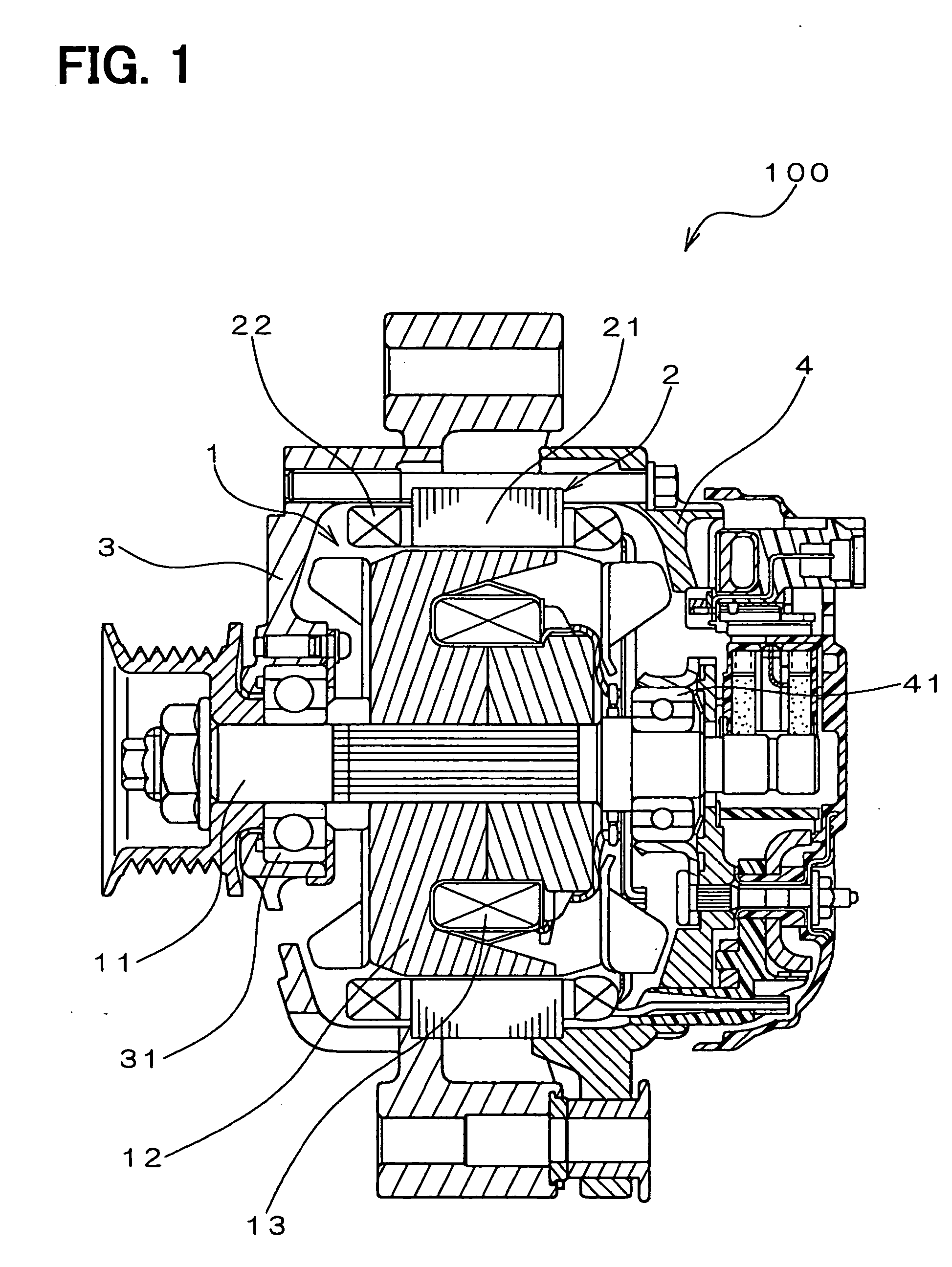
[0029] A preferred embodiment of the present invention will be described with reference to accompanying drawings. FIG. 1 shows an alternator (AC generator) for use in an automotive vehicle, to which the present invention is applied. The alternator 100 includes a rotor 1, a stator 2, a front bracket 3 and a rear bracket 4. The rotor 1 is composed of a rotor shaft 11, a pair of claw-shaped field cores 12 fixed to the rotor shaft 11, and a field winding 13 wound on the field cores 12. The stator 2 having a stator core 21 and stator windings 22 disposed in the stator core is positioned around the rotor 1 with a certain air gap therebetween. The stator 2 is sandwiched between the front bracket 3 and the rear bracket 4. The rotor 1 is rotatably supported by bearings 31, 41 held in the front bracket 3 and the rear bracket 4, respectively.

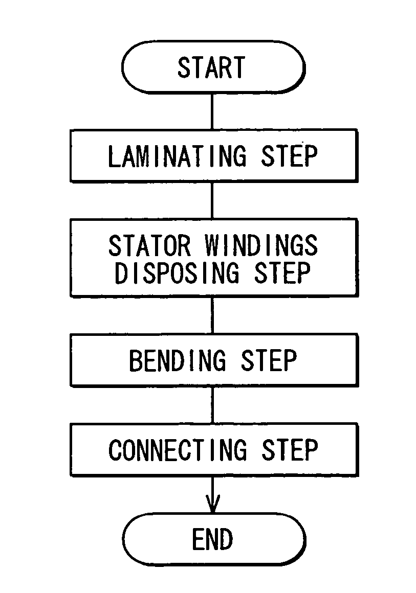
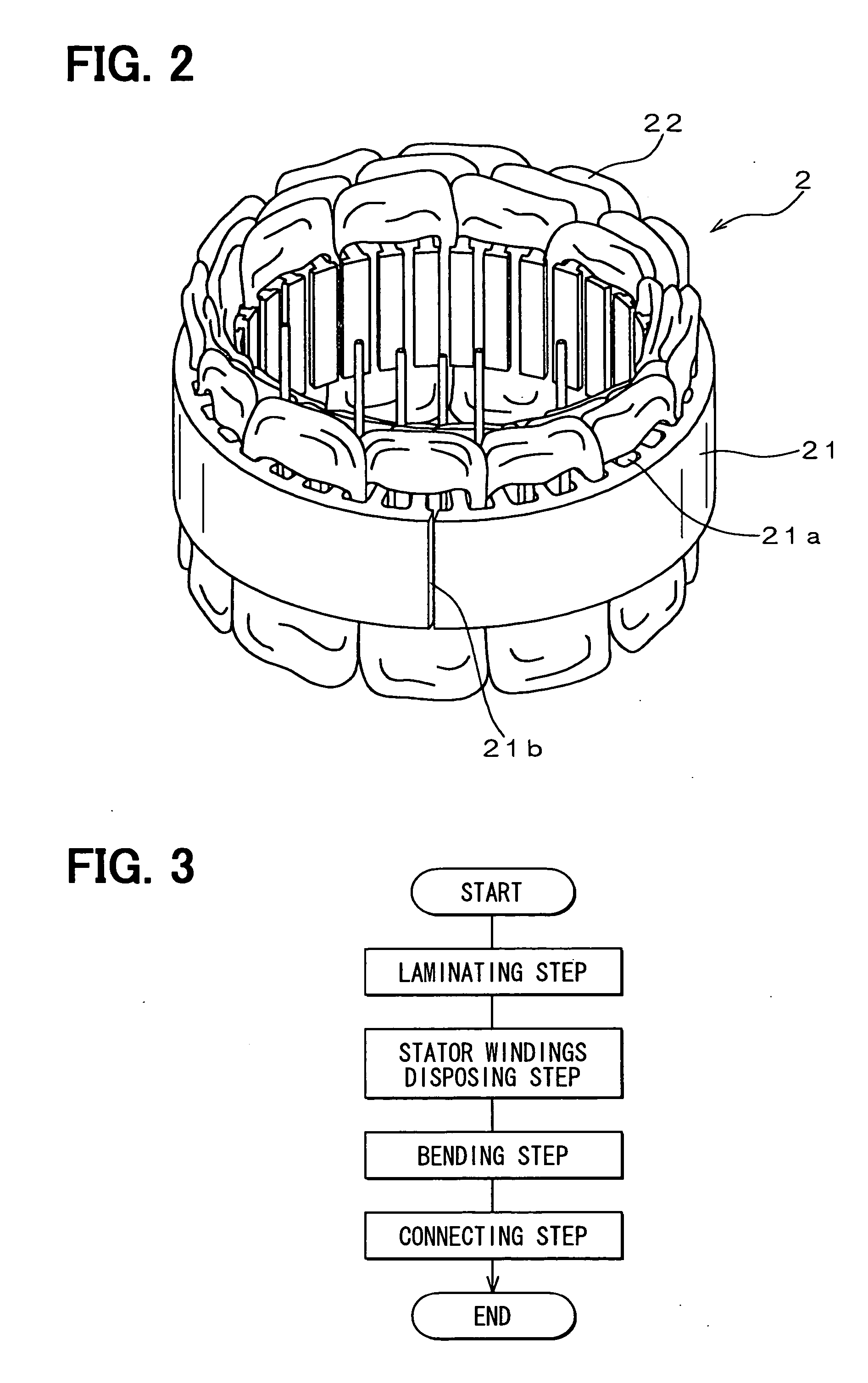
[0030]FIG. 2 shows an example of the stator 2 used in the alternator 100. The stator 2 is composed of a cylindrical stator core 21 and stator windings 22...


PUM

PropertyMeasurementUnit
thickaaaaaaaaaa
thickaaaaaaaaaa
thickaaaaaaaaaa

Abstract

A stator of a rotary electric machine is composed of a cylindrical stator core and stator windings inserted into slots of the stator core. A laminated body is formed by laminating steel sheets having slots and teeth. After stator windings in a flat shape are inserted into slots of the laminated body, the laminated body is bent into a cylindrical form along rollers between which the laminated body is sandwiched. In the bending process, positions of the teeth are restrained to prevent the stator windings disposed in the slots from being damaged by movement of the teeth. Alternatively, a bump extending from each tooth is formed, so that the tooth is restrained by gripping the bump in the bending process. The bumps are removed after completion of the bending process.

Description

CROSS-REFERENCE TO RELATED APPLICATION [0001] This application is based upon and claims benefit of priority of Japanese Patent Application No. 2005-176421 filed on Jun. 16, 2005, the content of which is incorporated herein by reference. BACKGROUND OF THE INVENTION [0002] 1. Field of the Invention [0003] The present invention relates to a method of manufacturing a stator of a rotary electric machine such as an automotive alternator. [0004] 2. Description of Related Art [0005] JP-A-9-103052 discloses an example of a method of manufacturing a stator of a rotary electric machine. This manufacturing method is composed of following steps: First, elongated sheets are formed by stamping a steel plate, each elongated sheet (about 20 mm wide and about 1 mm thick) having slots and teeth; then, elongated sheets are laminated into a rectangular-solid; then, stator windings in a flat shape are inserted (or disposed) in the slots; and then, the laminated rectangular-solid having the stator winding...

Claims


Application Information

Patent Timeline
Patent Type & Authority Applications(United States)
IPC IPC(8): H02K15/00
CPCH02K15/026Y10T29/49009Y10T29/49073
Inventor OOIWA, TOORU
Owner DENSO CORP
Why Eureka
Try Eureka