Food slicer with suction device and adjustable cutting surface

Inactive Publication Date: 2006-12-21
LIFETIME BRANDS
View PDF36 Cites 39 Cited by
  • Summary
  • Abstract
  • Description
  • Claims
  • Application Information

AI Technical Summary

Benefits of technology

[0011] The relative heights of the front of the rear platform and the blade are changed by moving a lever horizontally in a slot in the side of the slicer. The lever easily slides along a sloped flange on the rear platform of the slicer, thus raising and lowering the front of the rear platform. The lever is geared so that the changes in the relative heights of the blade and the

Problems solved by technology

Nevertheless, mandoline slicers are relatively large and take up considerable space when stored.
Mandoline slicers also have a tendency to move about on the counter when bulky, sticky, or relatively hard foods are being sliced, in which case the user must keep a solid grip on the slicer so that it does not move about during slicing.
If th

Method used


Image

  • Food slicer with suction device and adjustable cutting surface
  • Food slicer with suction device and adjustable cutting surface
  • Food slicer with suction device and adjustable cutting surface

Examples


Embodiment Construction

[0027] Certain terminology will be used in the following description. Words such as “top”, “bottom”, “upper”, “lower”, “upward”, “downward”, “rightward”, “leftward”, “above”, “below”, and the like, refer to those same directions in the properly oriented drawings. Words such as “inward”, “outward”, “inner”, “outer”, and “central”, refer to the same directions or locations at, toward, or away from the geometric center of the object shown or referenced in the properly oriented drawings. This use of such terminology is for convenient reference, is not intended to be limiting (as, for example, if an embodiment of the invention is inverted or reversed), and includes the words specifically mentioned, derivatives thereof, and words of a similar nature or import.

Slicer Assembly

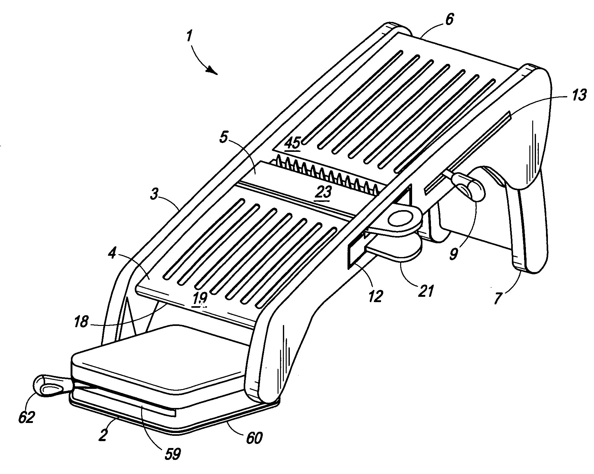
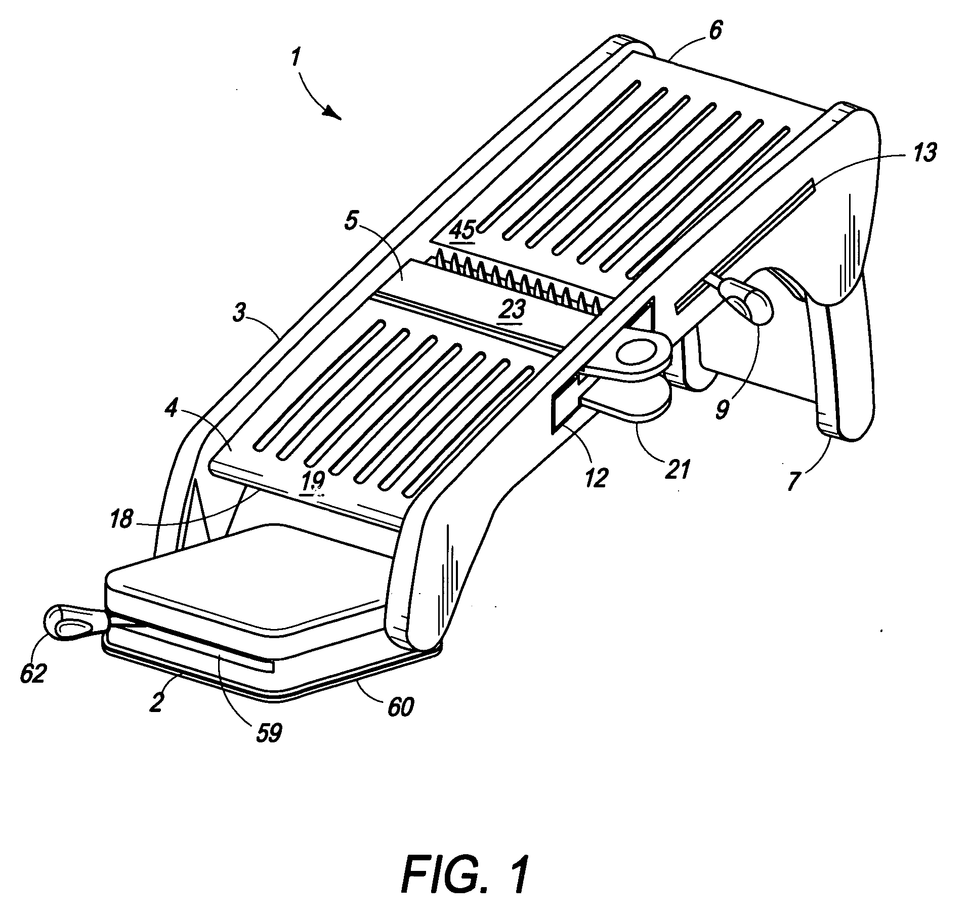
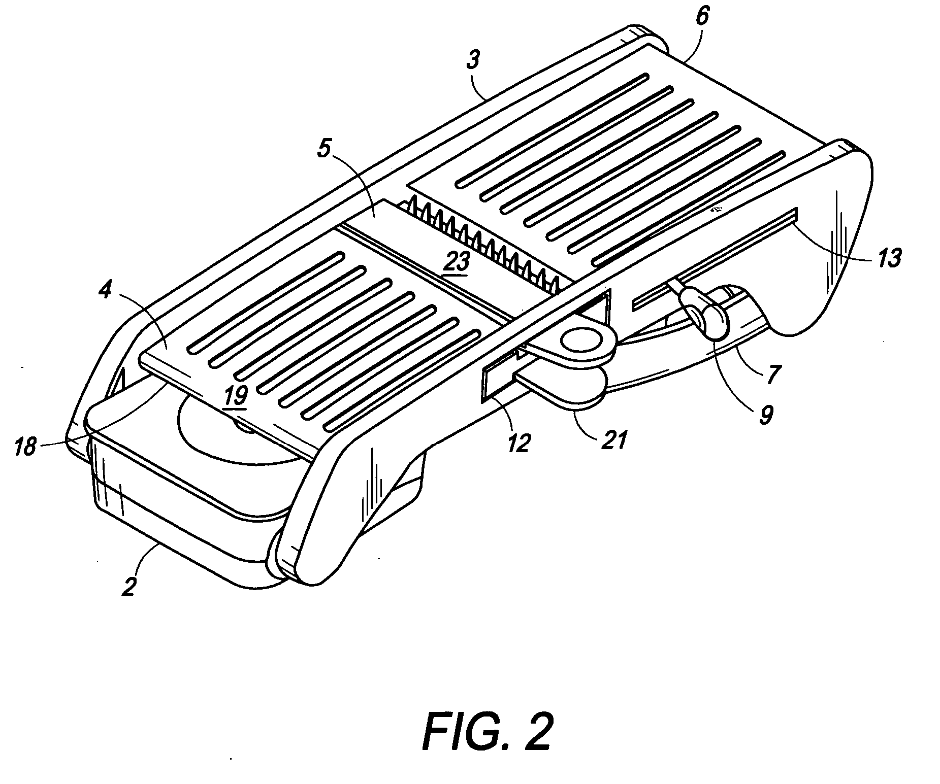
[0028]FIGS. 1, 5, and 8 show a slicer 1 of the invention. The slicer 1 has a suction device housing 2, a frame 3, a front platform 4, a blade 5, a rear movable platform 6, rear legs 7, a pivot 8, and a platform hand...


PUM

PropertyMeasurementUnit
Thicknessaaaaaaaaaa
Heightaaaaaaaaaa

Abstract

A mandoline slicer having a blade, a pivotable platform and a compact, low profile suction device in a housing that is hinged to the front of the slicer so that the suction device may be rotated under the slicer for storage and rotated at least partially outward from the front of the slicer for use. The height of a front edge of the platform is changed in relation of the height of the blade by moving a lever horizontally in a slot in a side of the slicer. The lever is geared so that the changes in the height of the front edge of the platform are incremental. Thus, the thickness of food slices moved over the platform and into the blade may be varied by know incremental amounts. Rear legs, which are foldable under the slicer for storage, contain compartments or slots for convenient, compact storage of slicer attachments.

Description

RELATED APPLICATIONS [0001] This application is a continuation-in-part of U.S. patent application Ser. No. 29 / 232,222, filed Jun. 16, 2005; U.S. patent application Ser. No. 29 / 232,229, filed Jun. 16, 2005; U.S. patent application Ser. No. 29 / 232,215, filed Jun. 16, 2005; U.S. patent application Ser. No. 29 / 232,220, filed Jun. 16, 2005; U.S. patent application Ser. No. 29 / 232,225, filed Jun. 16, 2005; U.S. patent application Ser. No. 29 / 232,321, filed Jun. 16, 2005; U.S. patent application Ser. No. 29 / 232,217, filed Jun. 16, 2005; U.S. patent application Ser. No. 29 / 232,271, filed Jun. 16, 2005; U.S. patent application Ser. No. 29 / 232,218, filed Jun. 16, 2005; U.S. patent application Ser. No. 29 / 232,248, filed Jun. 16, 2005; U.S. patent application Ser. No. 29 / 232,226, filed Jun. 16, 2005; U.S. patent application Ser. No. 29 / 232,228, filed Jun. 16, 2005; U.S. patent application Ser. No. 11 / 239,921, filed Sep. 30, 2005; and U.S. patent application Ser. No. 11 / 241,332, filed Sep. 30, 2...

Claims


Application Information

Patent Timeline
IPC IPC(8): B26D7/06B27B29/08
CPCB26D3/18B26D7/2628B26D7/00B26D3/283Y10T83/647Y10T83/652Y10T83/732Y10T83/9493
Inventor MELLEN, CHRISTOPHER M.HENRY, LOUIS F.
Owner LIFETIME BRANDS
Why Eureka
Try Eureka