Ultrasonic probe

a technology of ultrasonic probes and probes, applied in the field of ultrasonic probes, can solve the problems of difficult detection and reference position, complicated mechanically and structurally, and oscillating probes, and achieve the effect of simplifying the detection mechanism and simple detection

Inactive Publication Date: 2006-12-21
NIHON DEMPA KOGYO CO LTD
View PDF4 Cites 13 Cited by
  • Summary
  • Abstract
  • Description
  • Claims
  • Application Information

AI Technical Summary

Benefits of technology

[0022] The present invention enables detection of the boundary region of the optical rotary plated linked to the control shaft, to enable simple detection and setting of the reference of the group of piezoelectric elements. This enables a simple grasping of the position (rotational angle) in the short-axis direction of the group of piezoelectric elements from the reference position, by counting the number of pulsed generated by transmitting or blocking light by the optical rotary plate that is rotated by the stepping motor. This enables a simplification of the detection mechanism in the short-axis direction of the group of piezoelectric elements.
[0023] In accordance with the present invention, the optical rotary plate that acts as the reference position sensor has a light-blocking portion and a light-transmitting portion that are sequential in mutually opposite directions from the boundary region, and also this optical rotary plate rotates no further than a predetermined angle with reference to that boundary region. Since only one point of the boundary region is encountered during the rotation of the optical rotary plate, the boundary region that defines the reference position can be detected reliably.
[0025] Furthermore, it is possible to avoid damage to the flexible substrate and particularly breakage of the conductive path thereof because the protective cover, which prevents contact between the flexible substrate and the second bevel gear in accordance with this invention, covers the second bevel gear.

Problems solved by technology

However, the prior-art short-axis oscillating probe of this configuration has a problem in that it is complicated both mechanically and structurally and thus is expensive, since the rotational angle in the short-axis direction from the reference position of the group of piezoelectric elements 101 is detected by an optical encoder that is the rotational angle detection mechanism 103.
This raises a problem in that it becomes extremely difficult to detect and set the reference position.

Method used


Image

  • Ultrasonic probe
  • Ultrasonic probe
  • Ultrasonic probe

Examples


Embodiment Construction

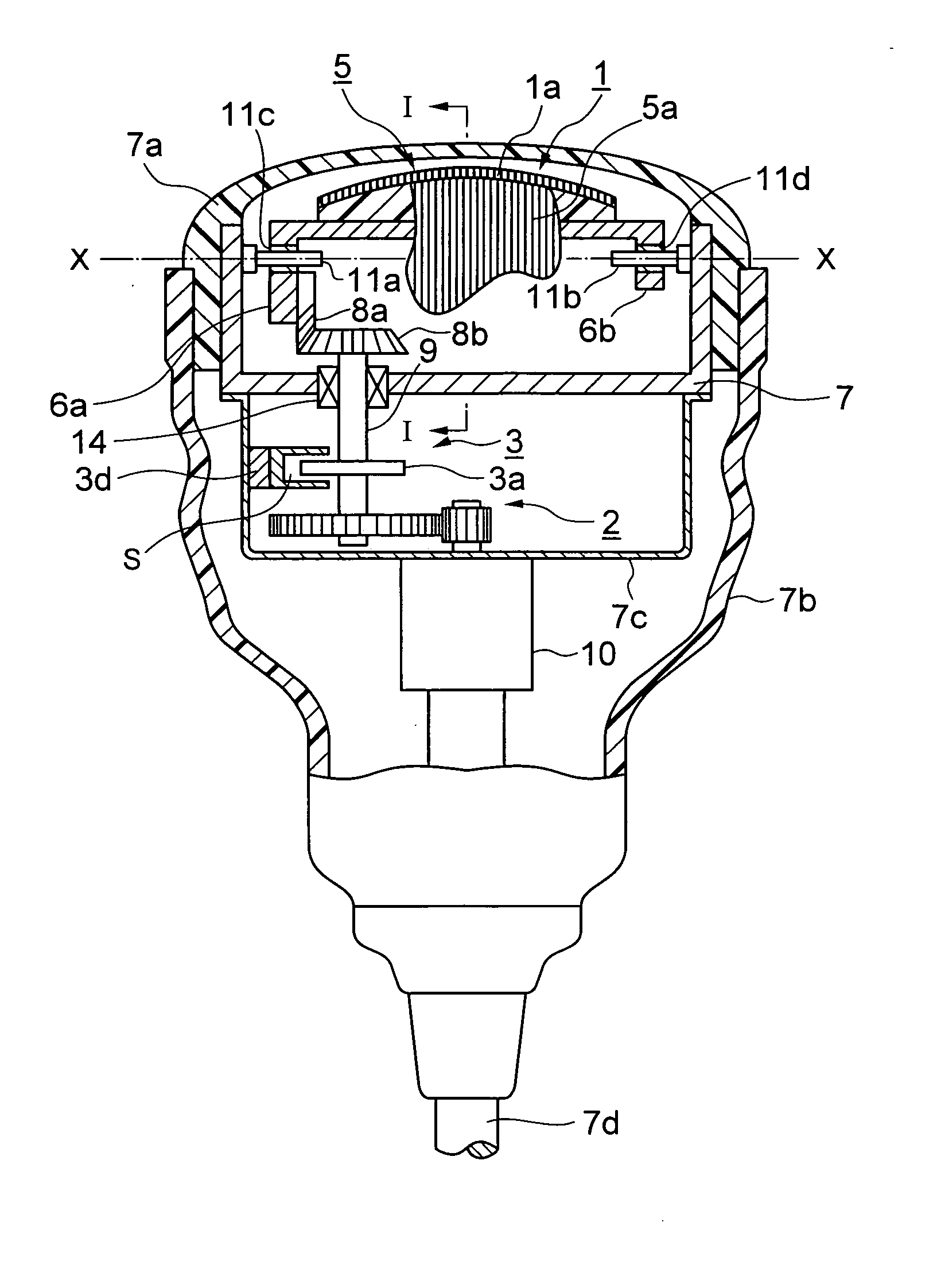
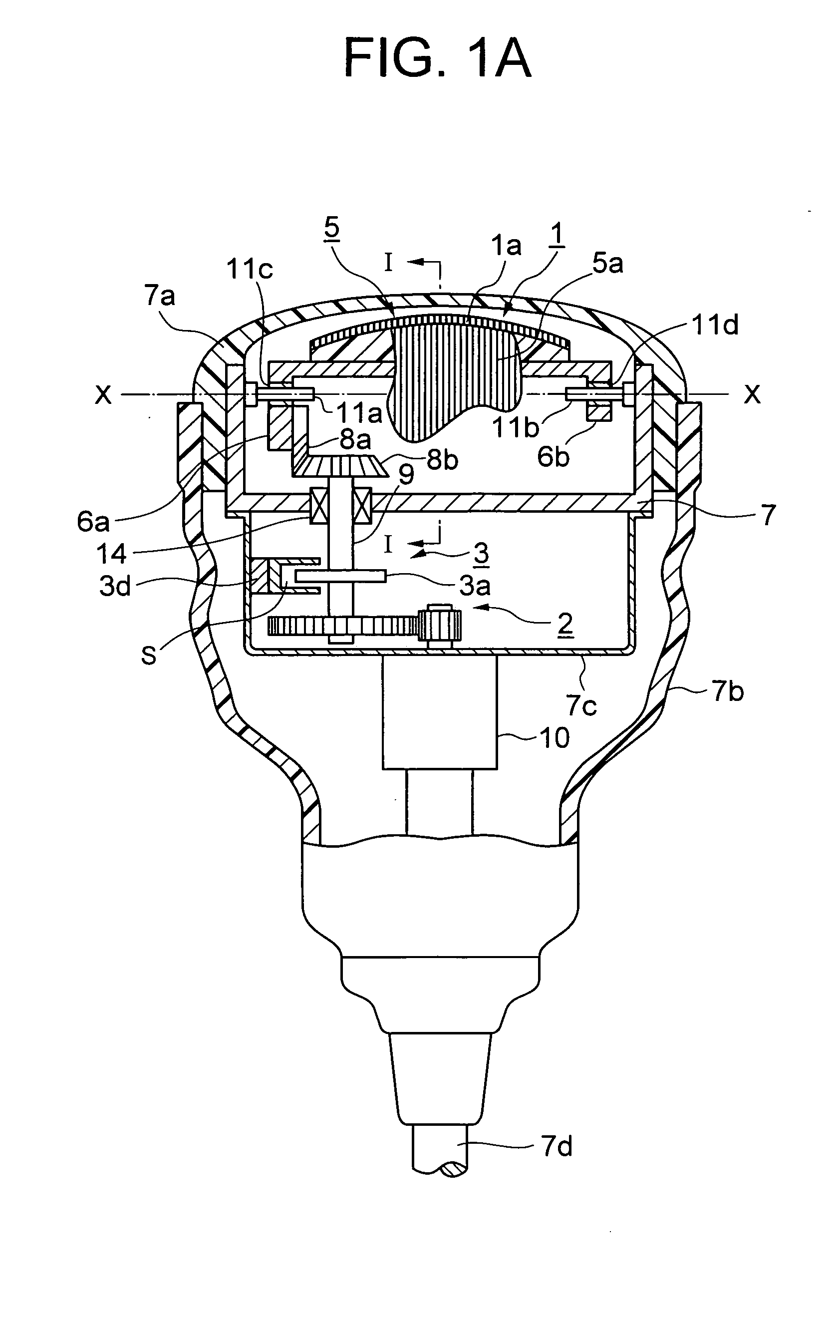
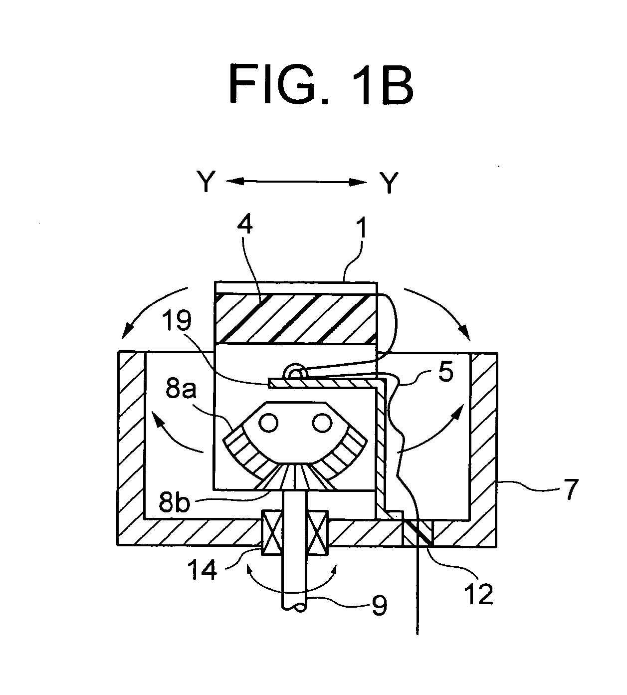
[0034] An embodying example of a short-axis oscillating probe in accordance with the present invention is shown in FIGS. 1A and 1B, where FIG. 1A is a partially cutaway section taken in the long-axis direction (X-X direction) of a short-axis oscillating probe having a rotational angle detection mechanism (reference position detection sensor) and FIG. 1B is a lateral section taken in the short-axis direction (Y-Y direction) of the rotational mechanism portion of the probe.

[0035] The short-axis oscillating probe of the present invention has a group of piezoelectric elements 1 consisting of a plurality of narrow card-shaped piezoelectric elements 1a arrayed in the long-axis direction of the probe (the X-X direction in FIG. 1A), with connecting wires such as a flexible substrate 5 extending outward therefrom, and a rotational mechanism portion 2 that rotates and oscillates in the short-axis direction thereof (in the Y-Y direction shown in FIG. 1B, perpendicular to the same plane that i...


PUM


Abstract

The invention relates to an oscillating ultrasonic probe that comprises a group of piezoelectric elements consisting of a plurality of narrow card-shaped piezoelectric elements arrayed in a long-axis direction and connecting wires such as a flexible substrate which are connected electrically to those piezoelectric elements and which extends outward from at least one end side in a short-axis direction; a rotational mechanism portion that causes the group of piezoelectric elements to rotate and oscillate to left and right in the short-axis direction about the center of the long-axis direction; a reference position detection sensor that detects a reference position in the short-axis direction of the group of piezoelectric elements; and a control shaft and a stepping motor linked to the reference position detection sensor and driving the rotational mechanism portion; wherein an optical rotary plate for the reference position sensor, which has a boundary region between a light-blocking portion and a light-transmitting portion, is linked to the control shaft; a light-blocking portion and a light-transmitting portion are formed sequentially at a predetermined angle in mutually opposite directions from the center of the optical rotary plate, with reference to a boundary region, and also the optical rotary plate rotates no further than a predetermined angle with reference to the boundary region. This configuration simplifies the mechanism for detecting the rotational angle of the group of piezoelectric elements, simplifies the detection of the reference position, and prevents damage to the flexible substrate.

Description

BACKGROUND OF THE INVENTION [0001] 1. Field of the Invention [0002] The present invention relates to an ultrasonic probe in which a group of piezoelectric elements oscillates in the short-axis direction of the probe to obtain a three-dimensional image (hereinafter called a “short-axis oscillating probe”) and, in particular, to a short-axis oscillating probe of a simple configuration that uses a stepping motor. [0003] 2. Description of Related Art [0004] A short-axis oscillating probe that is known in the art obtains a three-dimensional image by electronically scanning a group of piezoelectric elements in the long-axis direction of the probe and also by mechanically scanning (oscillating) the group of piezoelectric elements in that short-axis direction (see Japanese Patent Publication No. 7-38851 and Japanese Patent Laid-Open Publication No. 2003-175033). Since components such as wiring (connective wires) and scan circuitry of this type of short-axis oscillating probe can be configur...

Claims


Application Information

Patent Timeline
Patent Type & Authority Applications(United States)
IPC IPC(8): G21K7/00A61B8/00
CPCG01N2291/106G01N29/265A61B8/4461A61B8/483
Inventor HASEGAWA, YASUNOBU
Owner NIHON DEMPA KOGYO CO LTD
Why Eureka
Try Eureka