Axial member with flange, connection member and production methods thereof

a technology of axial member and connection member, which is applied in the direction of roofs, bumpers, vehicular safety arrangments, etc., can solve the problems of deterioration in structural rigidity, and achieve the effect of reducing weight and increasing energy absorption

Active Publication Date: 2006-12-21
KOBE STEEL LTD
View PDF9 Cites 36 Cited by
  • Summary
  • Abstract
  • Description
  • Claims
  • Application Information

AI Technical Summary

Benefits of technology

[0046] The connection member having the above configuration enables the axial member to be fixed to the flange members securely without inviting an extra increase in weight and prevents, for example, misregistration of the axial member. Forming holes for fixing the axial member in the first and second f

Problems solved by technology

Thus, looseness of a structure, such as a channel side-rail with a cross member or a bumper reinfor

Method used


Image

  • Axial member with flange, connection member and production methods thereof
  • Axial member with flange, connection member and production methods thereof
  • Axial member with flange, connection member and production methods thereof

Examples


Embodiment Construction

[0130] The axial members with flange according to the present invention will be illustrated with reference to FIGS. 1 to 10 by taking bumper stays as an example.

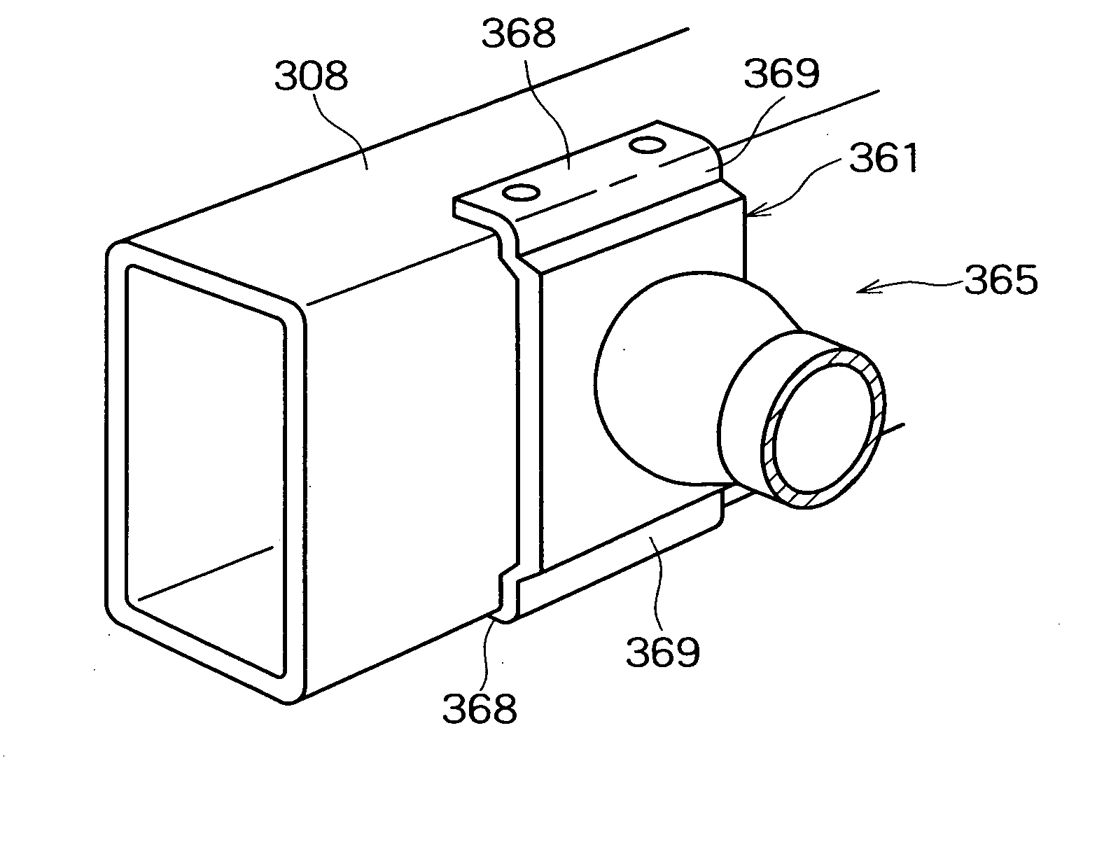
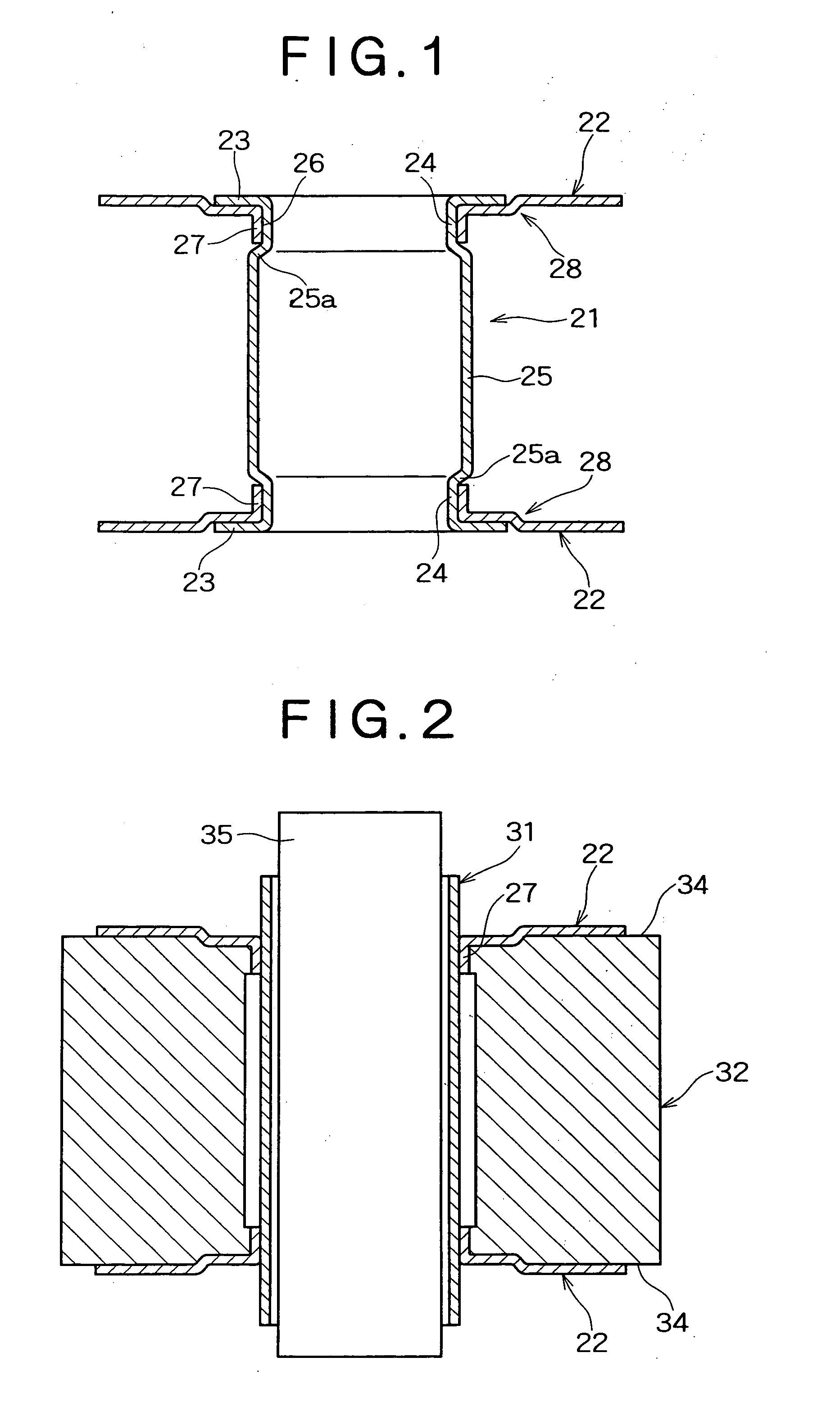
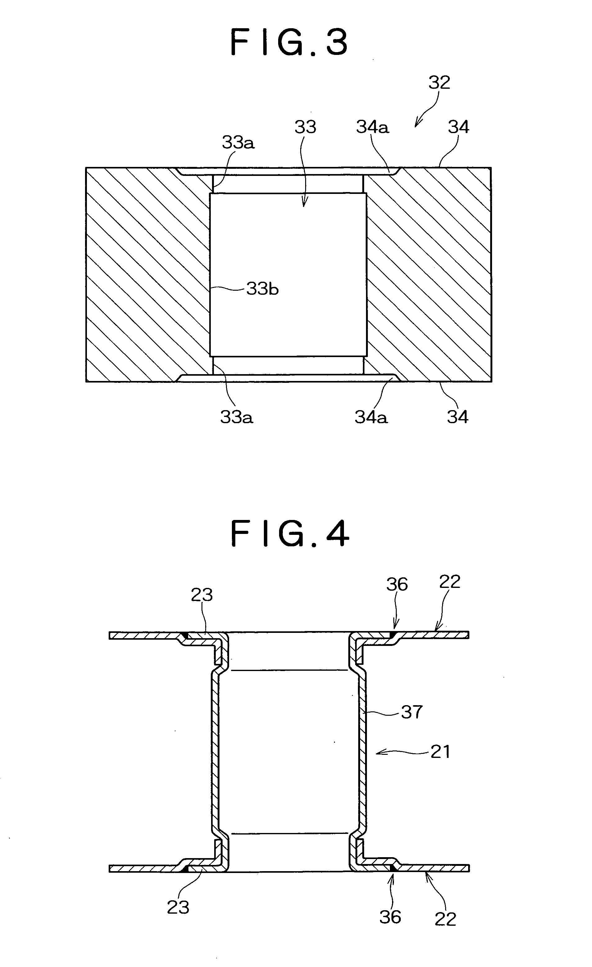
[0131] A bumper stay illustrated in FIG. 1 comprises an axial member 21 and a flange member 22. The axial member 21 is made of a tubular aluminum alloy extrudate. The flange member 22 is joined to the both ends of the axial member 21. The axial member 21 has end flanges (flared portions) 23 at its both ends. The end flanges 23 are integral with the axial member 21 and have an outer diameter less than that of the flange member 22. The axial member 21 has the minimum diameter in the vicinity of an end of an axial direction to constitute a small-diameter portion 24, and protrudes outward in a radial direction inside the small-diameter portion 24 to constitute a large-diameter portion (protrusion) 25. The flange member 22 has a hole 26 at its center part, into which the axial member 21 is to be inserted, and a cylindrical hole ...


PUM

PropertyMeasurementUnit
Lengthaaaaaaaaaa
Thicknessaaaaaaaaaa
Shapeaaaaaaaaaa

Abstract

A target tubular member with flange, such as a bumper stay, has a flange having an outer diameter larger than the diameter of an axial section and is formed by electromagnetic forming without excessive expansion. The tubular member with flange includes an axial member made of a tubular aluminum alloy extrudate and a flange member joined to an end of the axial member. The axial member has an end flange being integrated at its end and having an area smaller than that of the flange member. The flange member has a hole, and a cylindrical hole flange at the edge of the hole. The axial member fits in the hole of the flange member, the end flange is in intimate contact with the flange member, and the outer periphery of a small-diameter portion of the axial member is in intimate contact with the inner periphery of the hole flange. The hole flange is held between the end flange and a protrusion. The tubular member with flange may be produced by inserting an untreated pipe into the hole of the flange member and expanding the untreated pipe by electromagnetic forming.

Description

BACKGROUND OF THE INVENTION [0001] 1. Field of the Invention [0002] The present invention relates to axial members with flange having an axial section made of an aluminum alloy material and a mounting flange arranged at the end of the axial section, to connection members and to production methods of these members. [0003] 2. Description of the Related Art [0004] Bumpers arranged at the front end (front) and the rear end (rear) of bodies of automobiles such as passenger cars and trucks have bumper reinforcements as reinforcing members inside thereof. Such a bumper reinforcement is generally a member which is hollow in cross section and includes a front wall and a rear wall pointing substantially perpendicular to a loading direction, and a horizontal wall connecting these walls. The bumper reinforcement is supported by a pair of bumper stays from the rear, and the respective bumper stays are fixed at their rear end to the front end of the side member (front or rear). [0005] Aluminum bu...

Claims


Application Information

Patent Timeline
IPC IPC(8): B60R19/24
CPCB21D39/06B60R19/34B21D53/88
Inventor HASHIMOTO, NARIKAZUYOSHIDA, MASATOSHIYAMASHITA, HIROYUKINIMURA, SATOSHIHASHIMURA, TORUIMAMURA, YOSHIHAYAHORIGUCHI, KAZUMORI
Owner KOBE STEEL LTD
Why Eureka
Try Eureka