
Electrical machine and method of controlling the same

a technology of electric machines and control methods, applied in the direction of motor/generator/converter stoppers, dynamo-electric converter control, stopping arrangements, etc., can solve the problem of long time required during the align phas

Inactive Publication Date: 2006-12-21
REGAL BELOIT AMERICA
View PDF58 Cites 73 Cited by
  • Summary
  • Abstract
  • Description
  • Claims
  • Application Information

AI Technical Summary

Benefits of technology

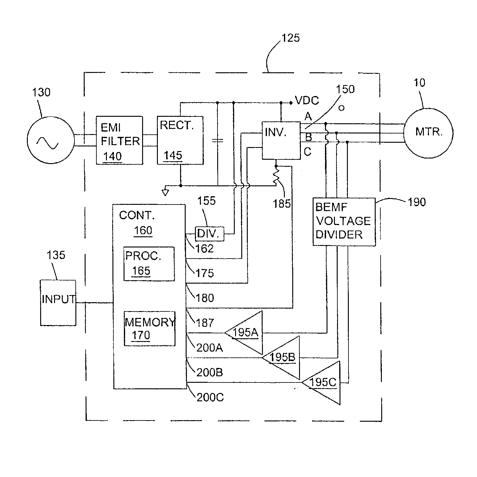
The patent text describes a method for controlling electrical machines, specifically BLDC motors, that allows for efficient and accurate positioning of the rotor without the need for a separate sensor. The method involves applying a pulsed voltage to the stator to cause movement of the rotor and monitoring the back electromotive force (BEMF) of the third phase to determine the direction of rotation. The method can be used in a variety of applications, such as heating and air conditioning, and can provide improved performance and efficiency compared to traditional methods.

Problems solved by technology

First, the time required during the align phase can be long where the inertia of the attached load is large and the friction is low (e.g., if the load is a large blower).

Method used


Image

  • Electrical machine and method of controlling the same
  • Electrical machine and method of controlling the same
  • Electrical machine and method of controlling the same

Examples


Embodiment Construction

[0023] Before any embodiments of the invention are explained in detail, it is to be understood that the invention is not limited in its application to the details of construction and the arrangement of components set forth in the following description or illustrated in the following drawings. The invention is capable of other embodiments and of being practiced or of being carried out in various ways. Also, it is to be understood that the phraseology and terminology used herein is for the purpose of description and should not be regarded as limiting. The use of “including,”“comprising,” or “having” and variations thereof herein is meant to encompass the items listed thereafter and equivalents thereof as well as additional items. The terms “connected,”“coupled,”“supported,” and “mounted” and variations thereof herein are used broadly and, unless otherwise stated, encompass both direct and indirect connections, couplings, supports, and mountings. In addition, the terms connected and co...


PUM


Abstract

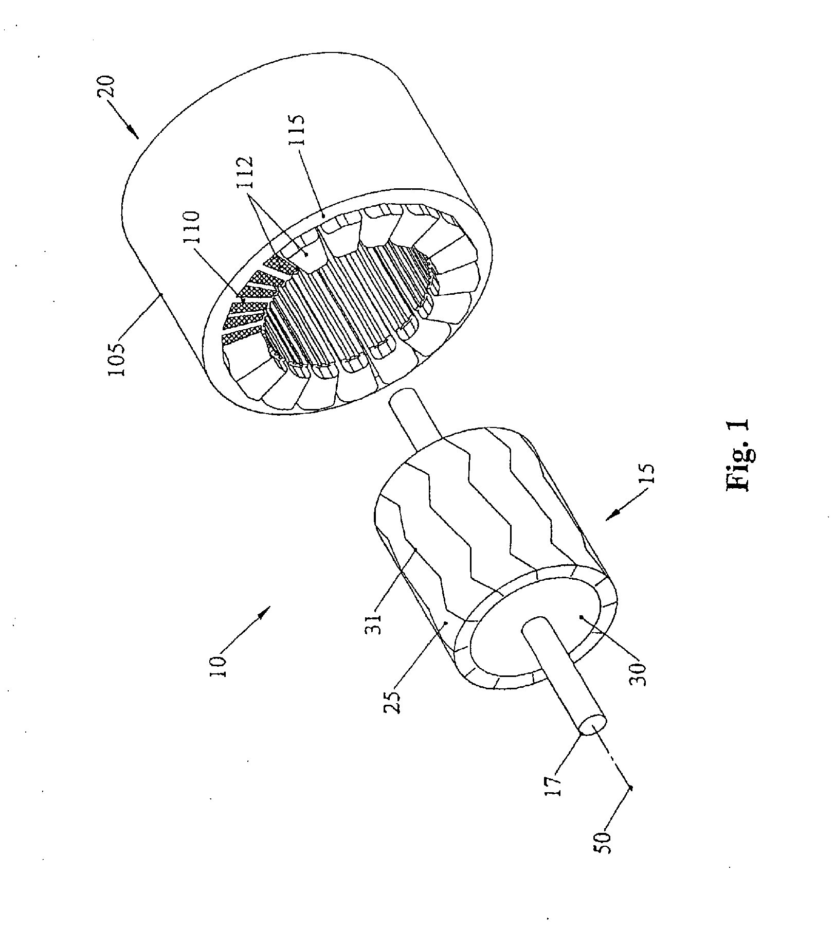
An electrical machine having a stator and a rotor. The stator includes a core and a plurality of windings disposed on the core in a multiple-phase arrangement. The rotor is disposed adjacent to the stator to interact with the stator. A method of operating the motor includes applying a pulsed voltage differential to first and second terminals of the windings resulting in movement of the rotor; monitoring the back electromotive force (BEMF) of the windings to sense rotor movement; after the applying and monitoring steps, monitoring the BEMF of the windings to determine whether the rotor is rotating in a desired direction, and electrically commutating the motor when the rotor is rotating in the desired direction and zero or more other conditions exist.

Description

RELEATED APPLICATIONS [0001] This application claims the benefit of U.S. patent application No. 60 / 734,855 filed on Nov. 9, 2005; and is a continuation-in-part of International Application No. PCT / US2004 / 034938 filed on Oct. 22, 2004, which claims the benefit of U.S. patent application No. 60 / 514,366 filed on Oct. 24, 2003.FIELD OF INVENTION [0002] The invention relates to an electrical machine and specifically a brushless electrical machine. BACKGROUND AND SUMMARY OF THE INVENTION [0003] Brushless direct current (BLDC) motors are becoming more prevalent in industries that typically did not use BLDC motors. For example, the need for increased efficiency in the heating and air conditioning market has led to the use of BLDC motors for powering the blower. BLDC motors include a rotor having a plurality of magnetic poles (e.g., a plurality of poles produced with permanent magnets) of alternating polarity disposed on a surface of a rotor core, and a stator that receives electrical power ...

Claims


Application Information

Patent Timeline
Patent Type & Authority Applications(United States)
IPC IPC(8): H02P3/00
CPCH02P3/08H02P6/24H02P6/182H02P3/18Y10S388/925
Inventor MULLIN, PAUL STEVENBRANECKY, BRIAN THOMAS
Owner REGAL BELOIT AMERICA
Learn More