
Cooling apparatus for electrostatic chuck

a technology of electrostatic chuck and cooling apparatus, which is applied in the direction of electrical apparatus, basic electric elements, semiconductor/solid-state device manufacturing, etc., can solve the problems of directly affecting the production yield of constituent semiconductor devices, the temperature of the electrostatic chuck to rise above acceptable tolerances, and damage to the wafer seated on the chuck, so as to improve and improve the cooling efficiency. , to achieve the effect of minimizing the variation of the temperature of the electrostatic chuck, the temperature o

Inactive Publication Date: 2006-12-21
SAMSUNG ELECTRONICS CO LTD
View PDF12 Cites 50 Cited by
  • Summary
  • Abstract
  • Description
  • Claims
  • Application Information

AI Technical Summary

Benefits of technology

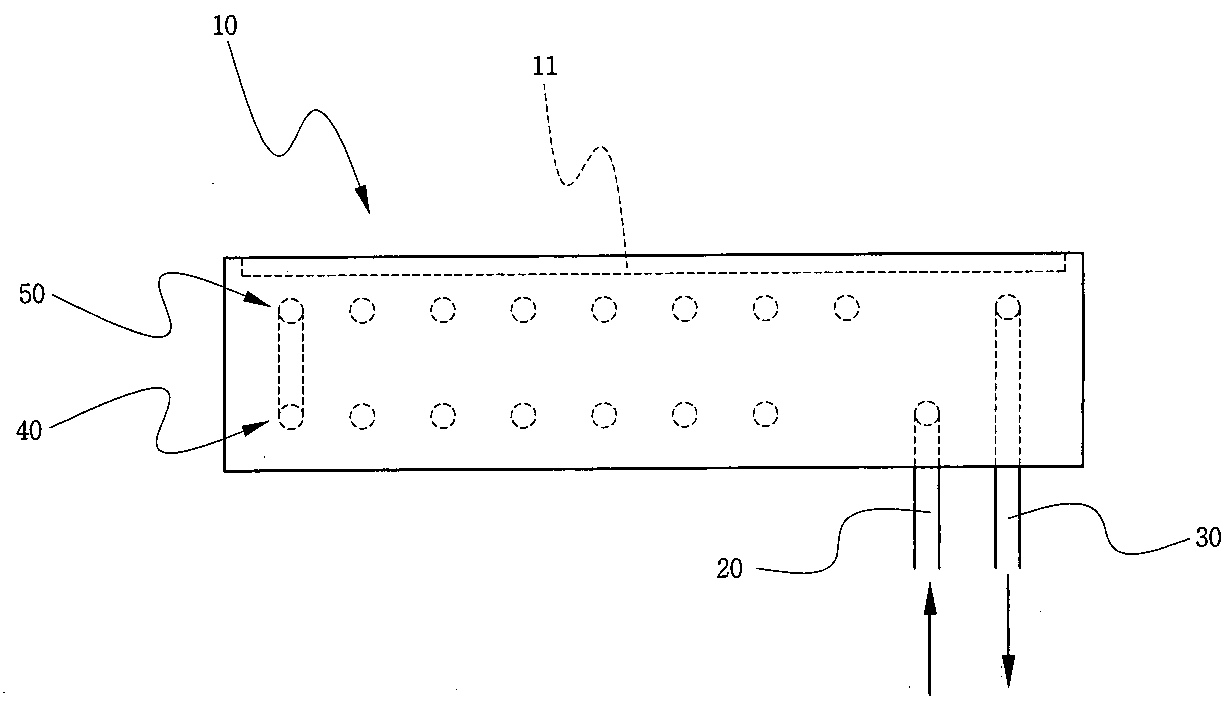
The invention provides an improved cooling apparatus for an electrostatic chuck used in semiconductor device fabrication. The apparatus includes a body with two cooling lines and a coolant supply and discharge pipes. The cooling lines circulate coolant to control the temperature of the chuck and minimize temperature variations. The technical effect is better controlled cooling efficiency and improved semiconductor device fabrication.

Problems solved by technology

Left without remedy, this generated heat would cause the temperature of the electrostatic chuck to rise above acceptable tolerances and potentially damage a wafer seated on the chuck.
Any change to a critical dimension may cause a circuit or component failure and directly affect production yield of the constituent semiconductor device.
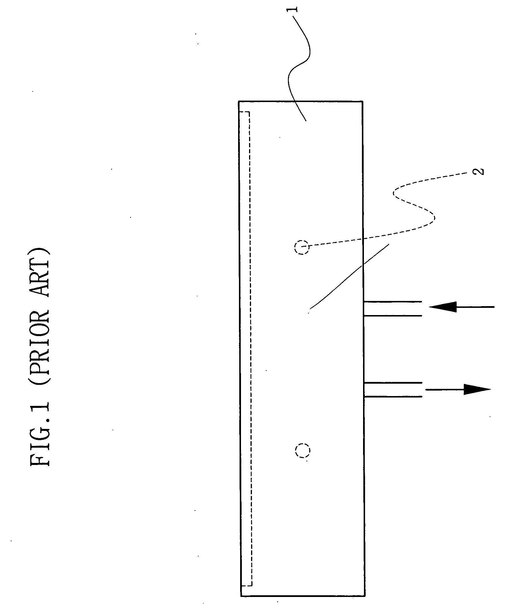
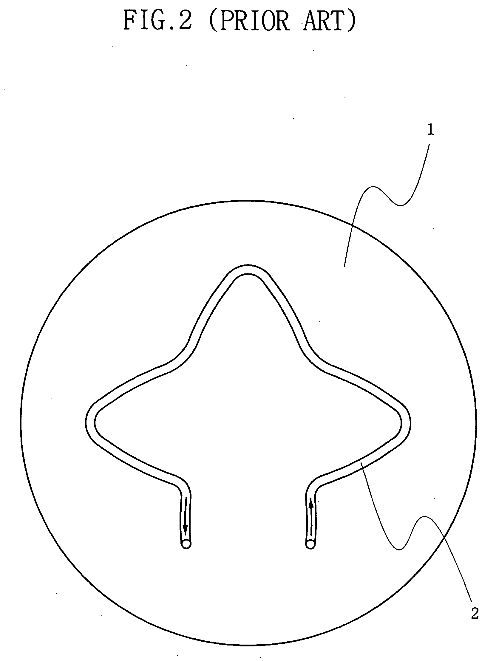
Such rapid exchange of coolant often leads to unpredictable cooling effects during some fabrication processes, or uneven cooling.
The resulting temperature variations of a wafer seated on the conventional electrostatic chuck may cause damage to circuits and / or components formed on the wafer.

Method used


Image

  • Cooling apparatus for electrostatic chuck
  • Cooling apparatus for electrostatic chuck
  • Cooling apparatus for electrostatic chuck

Examples


Embodiment Construction

[0024] Embodiments of the invention will now be described with reference to the accompanying drawings. The invention may, however, be embodied in many different forms and should not be construed as being limited to only the embodiments set forth herein. Rather, these embodiments are provided as teaching examples.

[0025]FIG. 3 is a side-sectional view illustrating an electrostatic chuck according to an embodiment of the invention. In FIG. 3, a body 10 of the electrostatic chuck may be made from an aluminum material, and a top surface of body 10 may include a plate 11 formed from a ceramic material. As further illustrated in FIG. 4, the exemplary body 10 is circular in shape

[0026] However, body 10 of the electrostatic chuck may be formed from any material and with any shape, so long as it is conducive to effective heat transfer and cooling efficiency. In addition, since body 10 will often be used as an RF electrode during certain fabrication processes, it should be formed of a conduc...


PUM


Abstract

An electrostatic chuck is disclosed with internal multi-level cooling lines or chambers circulating coolant.

Description

BACKGROUND OF THE INVENTION [0001] 1. Technical Field [0002] Embodiments of the invention relate to a cooling apparatus for an electrostatic chuck adapted for use in semiconductor fabrication equipment. More particularly, embodiments of the invention relate to a cooling apparatus for an electrostatic chuck that provides an even temperature distribution throughout the electrostatic chuck by improving a structure of associated cooling lines. [0003] This application claims the benefit of Korean Patent Application No. 10-2005-0053392, filed Jun. 21, 2005, the disclosure of which is hereby incorporated herein by reference in its entirety. [0004] 2. Discussion of Related Art [0005] Semiconductor devices are generally fabricated through a sequence of fabrication processes, such as photolithography processes, etching processes, deposition processes, diffusion processes, and ion implantation processes. Each of these fabrication processes is typically performed in specialized process chambers...

Claims


Application Information

Patent Timeline
Patent Type & Authority Applications(United States)
IPC IPC(8): H01L21/683
CPCH01L21/67109H01L21/68
Inventor LEE, IL-SOO
Owner SAMSUNG ELECTRONICS CO LTD
Learn More