Heating unit and the apparatus having the same

a heating unit and apparatus technology, applied in the field of heating units, can solve the problems of difficult realization, warping of the cooling module itself, and much disturbed temperature uniformity of the heater at the time of cooling, so as to improve the accuracy of thermal uniformity and minimize the temperature variation in the heater plane

Inactive Publication Date: 2010-02-25
SUMITOMO ELECTRIC IND LTD
View PDF4 Cites 6 Cited by
  • Summary
  • Abstract
  • Description
  • Claims
  • Application Information

AI Technical Summary

Benefits of technology

[0021]The present invention was made in view of the problems described above, and its object is to further improve accuracy of thermal uniformity of the object of heating during cooling, particularly during rapid cooling. By the improvement, particularly in the process of manufacturing a semiconductor device or / and flat display panel, temperature variation in the heater plane can be minimized when temperature conditions are changed to lower temperature side, and when a prescribed temperature has been reached, the heating process can be advanced immediately in accordance with the next conditions.
[0022]Another object is to further reduce the time required for changing the temperature during cooling, including stabilization of temperature variation in the plane, and further to improve productivity, performances, production yield and reliability of semiconductor devices and flat display panels manufactured through the process step of heat treatment.
[0023]In order to solve the above-described problems, the inventors have found through concentrated study that, by providing a heater substrate for mounting an object of heating and performing heat treatment thereon and a cooling module for cooling the heater substrate, and by arranging an intervening body between said heater substrate and the cooling module, the ratio of non-contact portions can be reduced than when the intervening body is not arranged, because of the deformability of the intervening body. It has been found that, though there are two layers of interfaces formed between the heater substrate and the cooling module, the state of contact can be improved and whereby temperature uniformity of the heater substrate can be improved at the time of cooling.

Problems solved by technology

In the conventional heater unit, however, though the main surface of the heater substrate has its surface roughness and flatness refined to mount the object of heating, the surface roughness and flatness of the rear surface of the heater substrate are not made so refined, in order to reduce cost for processing.
Further, unless the state of contact between heater substrate 2 and cooling module 3 is ideally sufficient over the entire contact surface, there arises a problem that temperature uniformity of the heater at the time of cooling is much disturbed, as the portion where the state of contact is perfect is cooled rapidly while the portion of imperfect contact is not easily cooled.
Consequently, cooling module 3 itself warps and contact with heater substrate 2 becomes even more unsatisfactory.
Further, when mobile cooling module 3 is brought into contact with heated heater substrate 2, it is difficult to realize, in industrial products at low cost, an ideal state of contact in which the surface is fully in ideal contact at one time without any inclined contact, or pressure of contact is uniform over the entire surface.

Method used


Image

  • Heating unit and the apparatus having the same
  • Heating unit and the apparatus having the same
  • Heating unit and the apparatus having the same

Examples


example 1

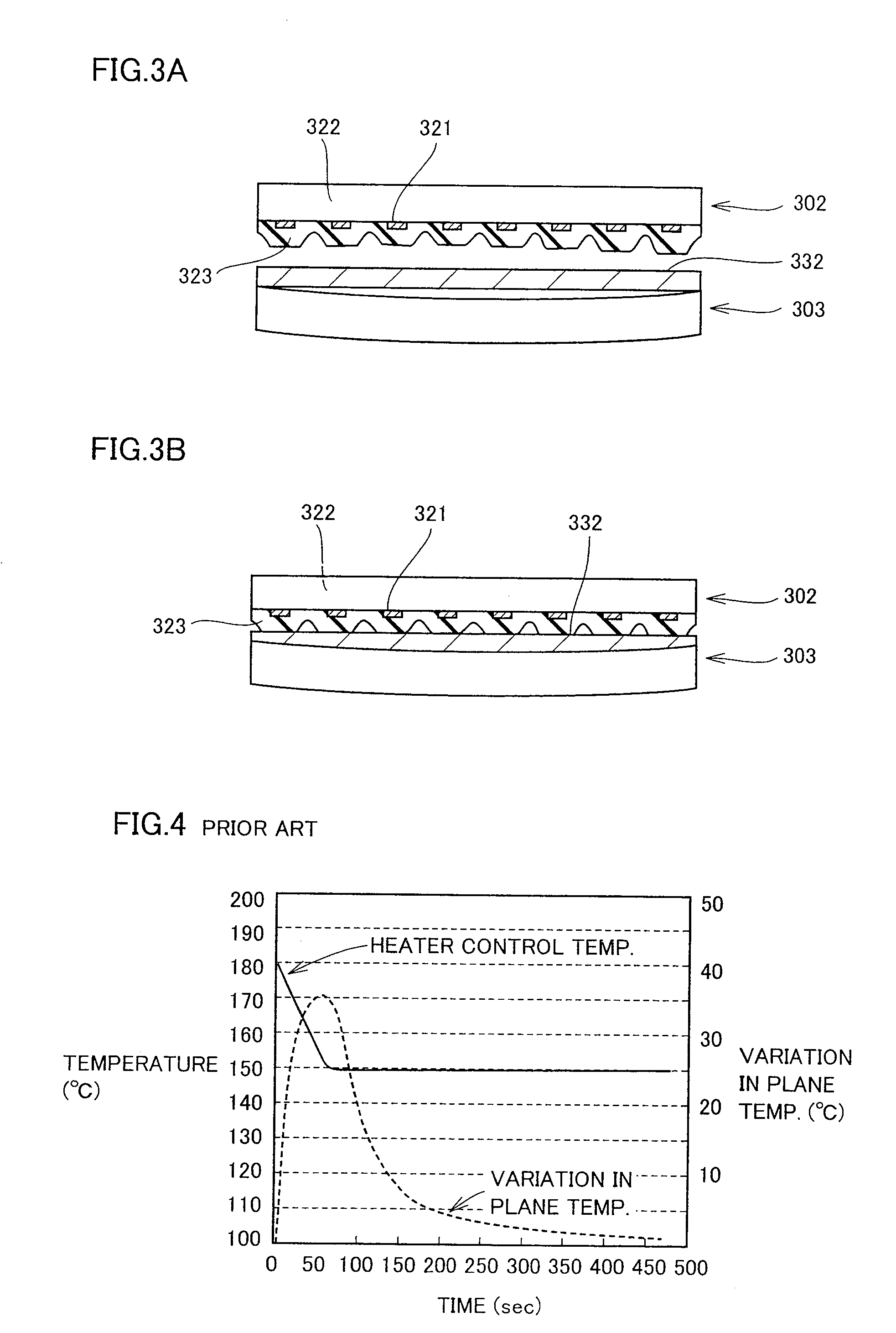
[0095]As an example in accordance with the present invention, a heater unit having a main portion structured as shown in FIGS. 3A and 3B and has the structure shown in FIG. 1 as a whole was fabricated. As heater base 322, 100 parts by weight of aluminum nitride powder and 0.6 parts by weight of yttrium stearate powder were mixed, 10 parts by weight of polyvinyl butyral as a binder and 5 parts by weight of dibutyl phthalate as a solvent were mixed, and spray-dried to form granules, which were press-molded, degreased in a nitrogen atmosphere at 700° C., sintered in a nitrogen atmosphere at 1850° C., and thus, an aluminum nitride sintered body was fabricated. The aluminum nitride powder used had average grain diameter of 0.6 μm and specific surface area of 3.4 m2 / g. The aluminum nitride sintered body was processed to have the diameter of 330 mm and the thickness of 12 mm.

[0096]Using 100 parts by weight of W powder having average grain diameter of 2.0 μm, 1 part by weight of Y2O3, 5 par...

example 2

[0107]Heater units similar to those of Example 1 were fabricated. Here, Ni cermet was used, and flatness of heater substrate 302 and flatness of cooling module 303 were varied as shown in Table 2, and variation in thermal uniformity at the time of cooling was measured. It was confirmed that desired thermal uniformity could be attained when flatness of both contacting surfaces was at most 300 μm.

TABLE 2Flatness ofFlatness ofCooling from 180° C.→150° C.heatercoolingThermal uniformityThermal uniformityRequiredType of interveningsubstratemodule60 sec. after cooling300 sec. after coolingcooling timebody(μm)(μm)(° C.)(° C.)(sec)DeterminationTarget————≦10° C.≦200 sec.Determined based onreferences on the leftComparativeNone352.750BexampleExamplesFoamNi cermet502001.20.895Ametal body1.0 mm1002001.20.8100A1502001.51.0108A2002001.61.0158A3002005.81.4180A40020015.22.8320B200501.10.7101A2001001.20.8106A2001501.61.0111A2003007.01.7169A20040015.53.0340B40040022.24.8450B

[0108]By mounting the heater...


PUM


Abstract

A heater unit that much improves accuracy in thermal uniformity of an object of heating during cooling, particularly rapid cooling, is provided. The heater unit in accordance with the present invention includes a heater substrate for mounting an object of heating and performing heat treatment thereon, and a cooling module for cooling the heater substrate, and between said heater substrate and the cooling module, an intervening body is arranged. Utilizing deformability of the intervening body, ratio of a non-contact portion can be reduced than when the intervening body is not provided, and temperature uniformity of the heater substrate at the time of cooling can be improved.

Description

[0001]This non-provisional application is based on Japanese Patent Application No. 2005-242210 filed with the Japan Patent Office on Aug. 24, 2005, the entire contents of which are hereby incorporated by reference.BACKGROUND OF THE INVENTION[0002]1. Field of the Invention[0003]The present invention relates to a heater unit used for heating a semiconductor substrate or a flat display panel substrate, as well as to a manufacturing / inspecting apparatus mounting the same, and particularly to a heat treatment apparatus used in the process step of photolithography, or a heat treatment apparatus used in the process step of final inspection of a semiconductor substrate.[0004]2. Description of the Background Art[0005]Many apparatuses mounting an object to be heated and performing heat treatment thereon have been developed. Among these, for an application requiring uniform temperature distribution (hereinafter referred to as thermal uniformity) of the object of heating, a heater unit has been...

Claims


Application Information

Patent Timeline
Patent Type & Authority Applications(United States)
IPC IPC(8): H05B3/68
CPCH05B3/265H01L21/67109
Inventor MIKUMO, AKIRAAWAZU, TOMOYUKIMATSUHARA, MASUHIRONAKATA, HIROHIKO
Owner SUMITOMO ELECTRIC IND LTD
Why Eureka
Try Eureka