Organic electroluminescent device

a technology of electroluminescent devices and organic materials, which is applied in the direction of discharge tube luminescnet screens, other domestic articles, organic chemistry, etc., can solve the problems of unsuitable compact equipment, low power consumption, and inability to receive clear information, so as to reduce the adhesiveness of cupc membranes, improve crystallinity, and enhance interfacial adhesiveness to anodes

Inactive Publication Date: 2006-08-31
HAYASHIBARA BIOCHEMICAL LAB INC
View PDF6 Cites 6 Cited by
  • Summary
  • Abstract
  • Description
  • Claims
  • Application Information

AI Technical Summary

Benefits of technology

[0040] Because of this, the present inventors concluded that such change in crystalline state of CuPc membrane arose after providing an amorphous hole injection layer, a hole transportation layer, a luminescent layer, an electron transportation layer and a cathode on CuPc membrane as crystalline hole injection layer (or after finishing a lu...

Problems solved by technology

Cathode-ray tubes are however large in both volume and weight and high in operation voltage, thus they may be unsuitable in compact equipments.
Liquid crystal devices however have the demerits that one can hardly receive a clear information therefrom when he or she views them at an angle outside the specific ranges, as well as that their power consumption is not so low as expected because they usually require backlight.
Many of organic EL devices proposed hitherto however have a problem of durability: Their brightness may decay within a short period of time when used under severe conditions, for example, in case of equipping them to cars and automobiles where mechanical vibrations and high temperatures are unavoidable.
In display panels which are driven in dot matrix mode and required for elevated brightness, any brightness decay would be one of serious problems: Such decay is most remarkable in green light-emitting devices which usually exhibit the highest brightness in full color panels.
3-(2-benzothiazolyl)-7-(diethylamino) coumarin, a typical...

Method used


Image

  • Organic electroluminescent device
  • Organic electroluminescent device
  • Organic electroluminescent device

Examples


example 1

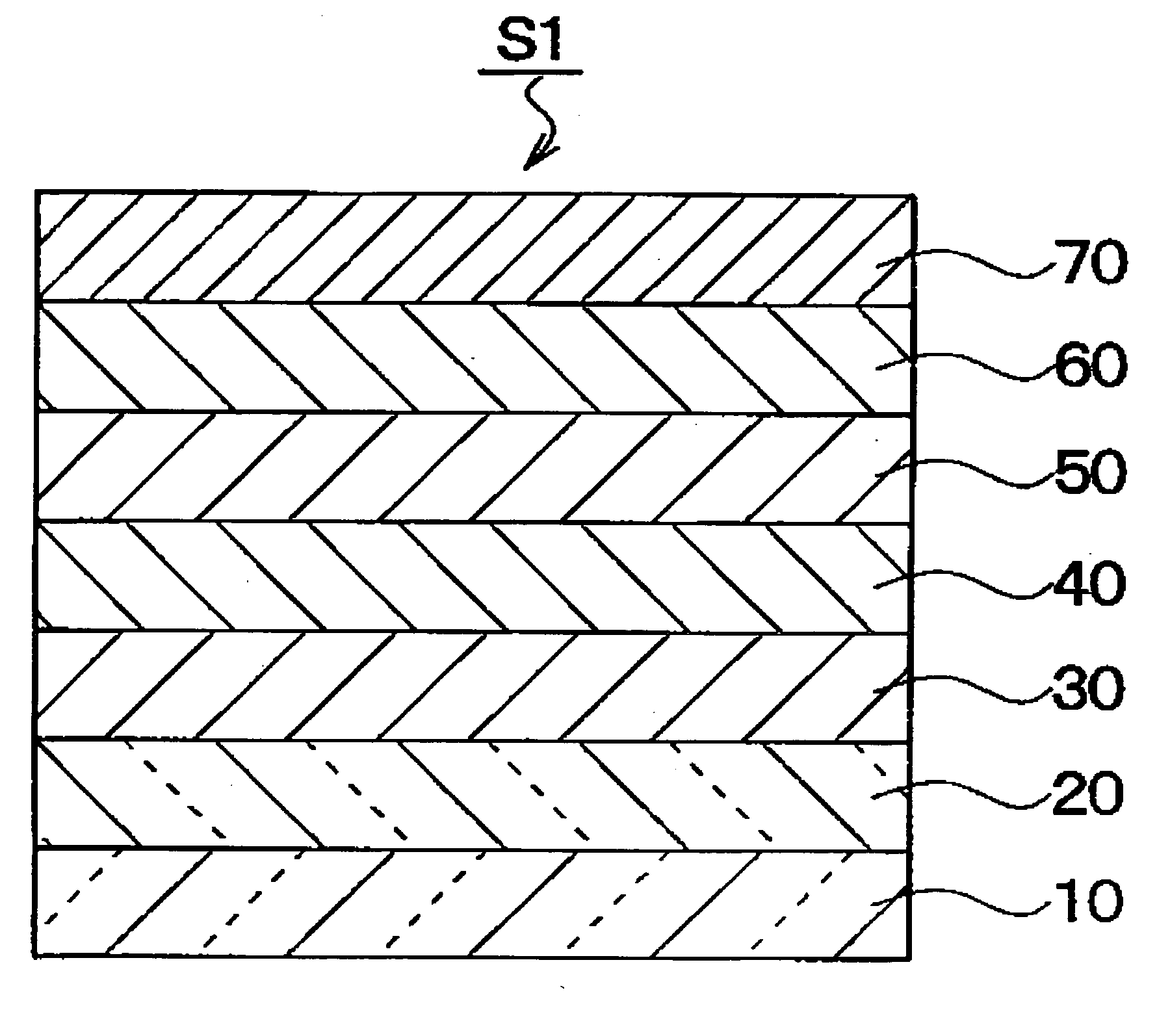
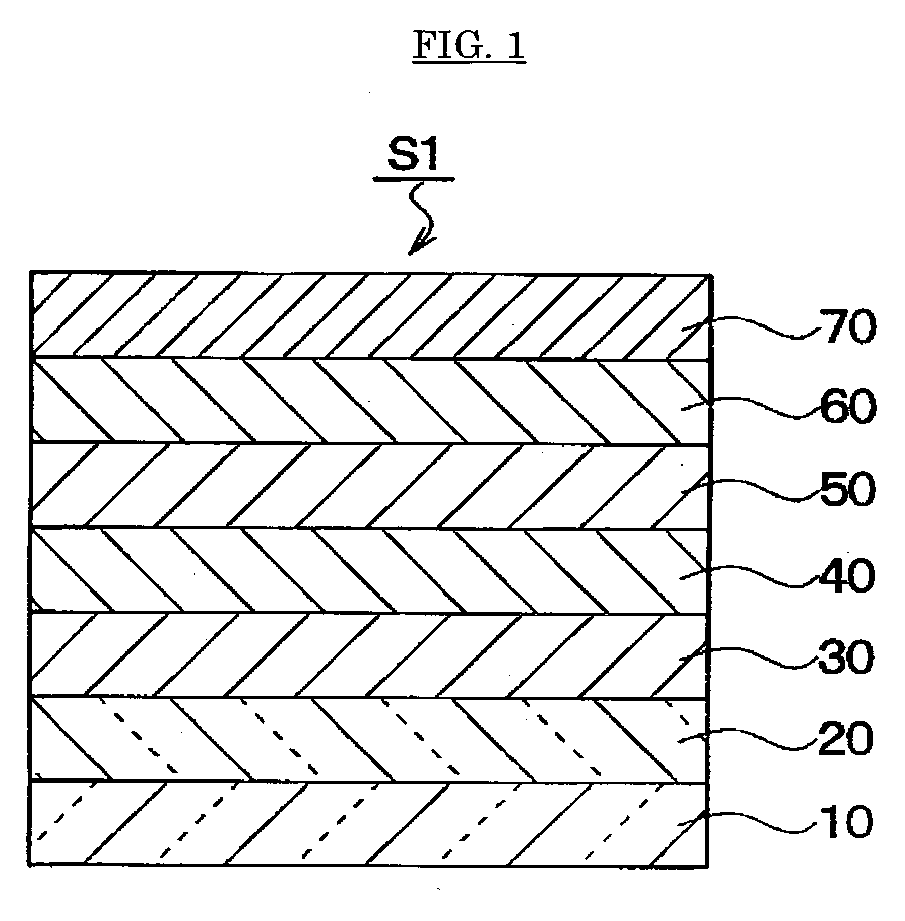
[0147] The anode 20 of ITO, thickness of 150 nm, is formed on the substrate 10 of glass by the spattering method. After patterning, the surface of ITO is smoothed by grinding: The mean height of surface roughness profile (Ra) of ITO is preferably to be 2 nm or less, while its ten point mean height of surface roughness profile (Rz) is to be 20 nm or less. This example uses an ITO where the surface has been ground to an Ra of about 1 nm or less and an Rz of about 10 nm.

[0148] On the anode 20 is formed the hole injection layer 30 of copper phthalocyanine, thickness of 15 nm, by the vacuum vapor deposition method. Further, the hole transportation layer 40 of triphenylamine tetramer represented by Chemical Formula 10, thickness of 40 nm, is formed by the vacuum vapor deposition method.

[0149] Thereafter, formed is the luminescent layer 50, thickness of 40 nm, which consists of 2% by mass of the coumarin derivative 1 represented by the above Chemical Formula 7 as dopant, 49% by mass of ...

example 2

[0152] A green light-emitting device was obtained similarly as in Example 1, except that it used the luminescent layer 50, thickness of 40 nm, which consists of 2% by mass of the coumarin derivative 1 represented by the Chemical Formula 7 as dopant, 94% by mass of Alq3 as host material, and 4% by mass of triphenylamine tetramer. The chromaticity was (0.28, 0.62) on the chromaticity diagram established by CIE.

[0153] The brightness half life was 1,500 hours when the device was continuously allowed to emit luminescence at 85° C. and 400 Cd / m2 in 1 / 64 duty driving mode. As described above, this Example attained an organic EL device which had an enhanced durability at elevated temperature and consistently emitted a visible light in the green region over a long period of time even when driven under elevated temperature conditions.

[0154] Further, in this Example an organic EL device superior in durability to that in Example 1 was attained because the mixing ratio against host in the lumi...

example 3

[0157] A green light-emitting device was obtained similarly as in Example 1 except that it used the luminescent layer 50, thickness of 40 nm, which consists of 1% by mass of the coumarin derivative 2 represented by the Chemical Formula 8 as dopant, 74% by mass of Alq3 as host material, and 25% by mass of triphenylamine tetramer. The chromaticity was (0.27, 0.60) on the chromaticity diagram established by CIE.

[0158] The brightness half life was 1,000 hours when the device was continuously allowed to emit luminescence at 85° C. and 400 Cd / m2 in 1 / 64 duty driving mode. As described above, this Example attained an organic EL device which had an enhanced durability at elevated temperature and consistently emitted a visible light in the green region over a long period of time even when driven under elevated temperature conditions.


PUM

PropertyMeasurementUnit
Temperatureaaaaaaaaaa
Fractionaaaaaaaaaa

Abstract

This invention has an objective to improve durability at elevated temperature in organic electroluminescent devices using coumarin derivatives as dopant in a luminescent layer. This invention attains the above objective by providing in the organic electroluminescent devices formed by laminating an anode, a hole injection layer, a hole transportation layer, a luminescent layer, an electron transportation layer and a cathode in this order, the luminescent layer which comprises as dopant the green light-emitting coumarin derivative and hole- and electron-transporting substances as host; said coumarin derivative consisting of a plurality of coumarin groups bound to an aromatic ring, heterocycle, or any combination thereof, and exhibiting a glass transition point of 150° C. or higher or a melting point of 297° C. or higher.

Description

TECHNICAL FIELD [0001] The present invention relates to an organic electroluminescent device (abbreviated as “organic EL device” hereinafter) where a coumarin derivative is used as dopant in the luminescent layer of the organic EL device. BACKGROUND ART [0002] In this age of the growing importance of information, organic EL devices have been highlighted as displaying device of the next generation. Hitherto, cathode-ray tubes have been predominantly used in information displaying equipments in larger sizes. Cathode-ray tubes are however large in both volume and weight and high in operation voltage, thus they may be unsuitable in compact equipments. [0003] More required are information displaying equipments which are in a thinner and lighter panel form and operable with a lower voltage and less power consumption. Liquid crystal devices have been extensively used in various fields because of the merit that they are operable with a lower voltage and less power consumption. [0004] Liquid...

Claims


Application Information

Patent Timeline
IPC IPC(8): H01J1/62C07D491/16H01L51/50C09K11/06H01L51/00H01L51/30H01L51/40H05B33/14
CPCC07D311/16C07D407/10C09K11/06C09K2211/1029C09K2211/1088H01L51/002Y10S428/917H01L51/0061H01L51/0065H01L51/0071H01L51/5012H05B33/14H01L51/006H10K71/30H10K85/653H10K85/636H10K85/633H10K85/657H10K50/11H05B33/22
Inventor KOJIMA, KAZUSHIGETACHI, KOJIROFUJIKAWA, HISAYOSHINODA, KOJIISHII, MASAHIKOTAGA, YASUNORISATSUKI, MAKOTOFUJIWARA, MAKOTOISHIDA, NATSUKOSUGA, SADAHARU
Owner HAYASHIBARA BIOCHEMICAL LAB INC
Why Eureka
Try Eureka