Ceiling fan light LED assembly device

Inactive Publication Date: 2006-12-21
SHYU SHING JY
View PDF5 Cites 51 Cited by
  • Summary
  • Abstract
  • Description
  • Claims
  • Application Information

AI Technical Summary

Benefits of technology

[0007] The present invention is to provide a ceiling fan light LED (light emitting diode) assembly device, characterized in that a drive circuit, which enables light-emitting bodies to emit illumination light, and a pull chain switch, which controls rotating of a fan of a suspended mount and a cutover switch action, are disposed within a holding space of a mount disc. When a pull chain of the pull chain switch effectuates a cutover switch action, the pull chain switch thereupon actuates the drive circ

Problems solved by technology

Moreover, a relatively high voltage is needed when the light tubes disposed within the light body A2 are emitting light, thus, operating life

Method used


Image

  • Ceiling fan light LED assembly device
  • Ceiling fan light LED assembly device
  • Ceiling fan light LED assembly device

Examples


Embodiment Construction

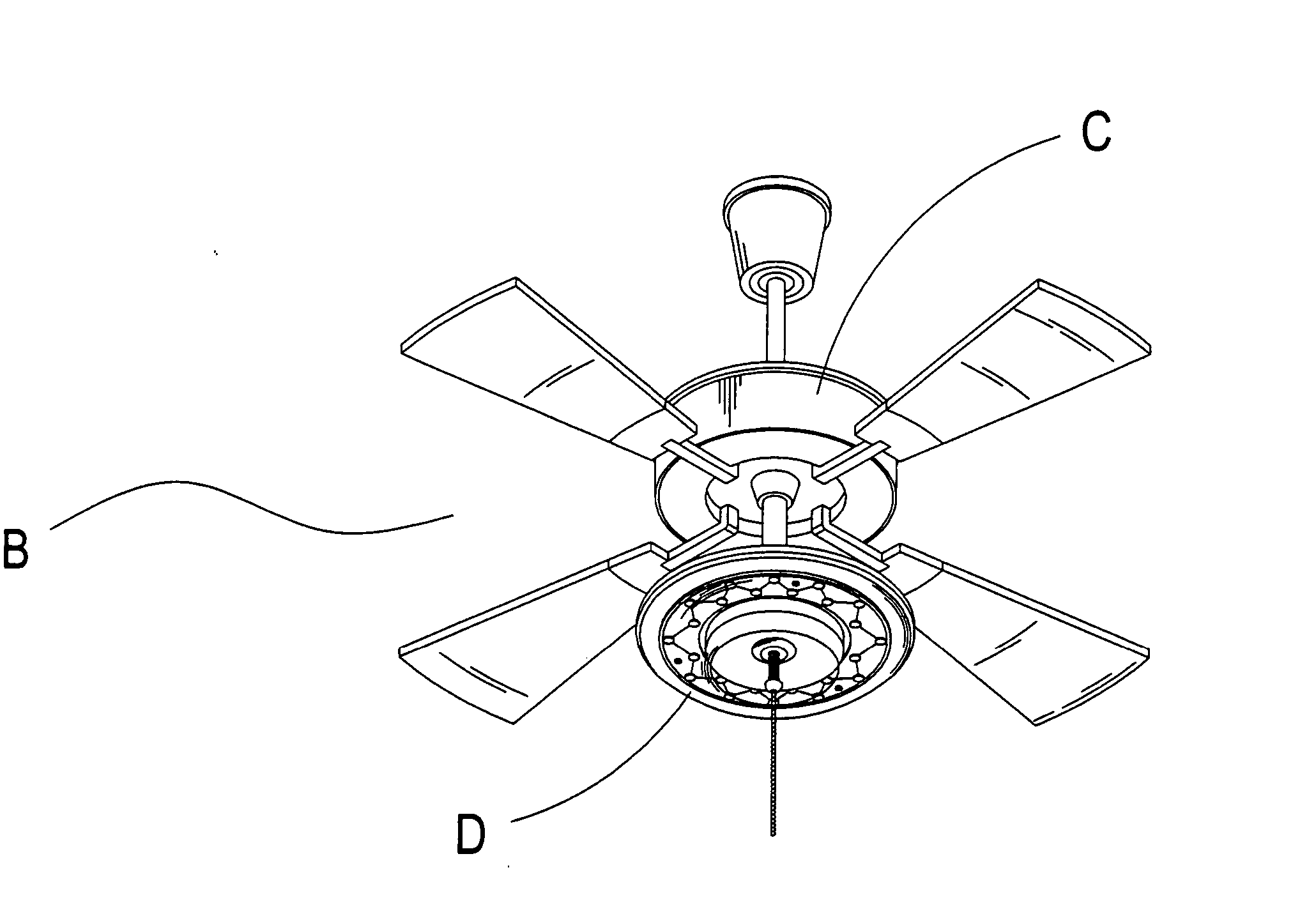
[0020] Referring to FIG. 3, which shows a ceiling fan light LED (light emitting diode) assembly device of the present invention, wherein a ceiling fan light B is structured to comprise a suspended mount C and a light body D. Referring to FIG. 4, which shows the light body D structured to comprise a locking disc E, a mount disc F, a reflecting protective cover F6, a circular light mount G, light-emitting bodies H, a transparent shade I and a nut J.

[0021] When assembling the light body D of the suspended mount C, a drive circuit F2 and a pull chain switch F3 are disposed between the locking disc E and the mount disc F. Moreover, the circular light mount G and the light-emitting bodies H are affixed to a periphery of a holding space F1 using securing bolts F5. When assembling the locking disc E, the mount disc F, the reflecting protective cover F6, the circular light mount G and the light-emitting bodies H, screws K are used to screw down the locking disc E to the mount disc F, and a ...


PUM


Abstract

A ceiling fan light LED assembly device, wherein a plurality of light-emitting bodies are disposed within light tubes, and a drive circuit within a mount disc directly actuates the light-emitting bodies to emit light. Furthermore, a reflecting protective cover having a light focusing and refracting effect is disposed on the mount disc, which is not only able to transmit light emitted by the light-emitting bodies H through the reflecting protective cover F6, but is also able to transmit the light through an arched surface of the transparent shade I, thereby enhancing illumination effectiveness of the refracted light rays.

Description

BACKGROUND OF THE INVENTION [0001] (a) Field of the Invention [0002] The present invention relates to a ceiling fan light LED (light emitting diode) assembly device, characterized in that a drive circuit, which enables light-emitting bodies to emit illumination light. [0003] (b) Description of the Prior Art [0004] Referring to FIGS. 1 and 2, which show a conventional ceiling fan light A including a light body A2 mounted on a suspended mount A1. The light body A2 is configured with illuminating light tubes A3, which are affixed to the light body A2 using fasteners A4. A controller A5 and a pull chain switch A6, which are disposed within the light body A2, and a pull chain A7 of the pull chain switch A6 are used to actuate a cutover switch action that simultaneously causes a fan affixed to the suspended mount A1 to rotate and the light tubes A3 to emit illumination. [0005] The light tubes A3 disposed within the light body A2 are manufactured from glass with the addition of lead, fluor...

Claims


Application Information

Patent Timeline
IPC IPC(8): F21V33/00
CPCF04D25/088F04D29/005F21Y2101/02F21V33/0096F21Y2115/10
Inventor SHYU, SHING-JY
Owner SHYU SHING JY
Why Eureka
Try Eureka