Supercharge Your Innovation With Domain-Expert AI Agents!

Bifurcation stent delivery catheter assembly and method

a stent and catheter technology, applied in the field of stents and systems, can solve the problems of stent deployment assembly, which supports and transports the stent in a collapsed state, is not rotatably controlled, and the stent is delivered and deployed relative to the side branch, so as to achieve convenient radial alignment, improve the ability to unwind, and reduce the resistance

Inactive Publication Date: 2006-12-21
ABBOTT LAB INC
View PDF5 Cites 6 Cited by
  • Summary
  • Abstract
  • Description
  • Claims
  • Application Information

AI Technical Summary

Benefits of technology

The present invention is a stent delivery system that allows for easy and accurate placement of a stent in a body vessel. The system includes an elongated shaft and a stent deployment assembly with a rotational clutch assembly. The clutch assembly is designed to transmit torsional forces between the shaft and the deployment assembly, allowing for easy alignment and deployment of the stent. The system also includes a flexible protective boot device and a first and second guidewire lumen for sliding receipt of the guidewires in the body vessel. The clutch assembly may include a flexible stiffening element and an outer and inner tubular flexible member for transmitting compressive forces between the shaft and the transition portion. The system also includes a plurality of coils and a fluid impermeable sealing member for sealing the clutch assembly. The technical effects of the invention include improved placement accuracy, improved maneuverability, and improved protection of the stent during advancement through the body vessel.

Problems solved by technology

While these bifurcation stent designs have encountered varying degrees of success, one major problem associated with all bifurcation systems is that the delivery and deployment of the stent, relative to the side branch, is extremely difficult.
This is due primarily to the difficulty in properly controlling the orientation, alignment and position of the stent deployment assembly relative to the main branch and side branch of the bifurcated vessel.
During advancement of the catheter shaft along the predisposed guidewire, the stent deployment assembly, which supports and transports the stent in a collapsed state, is not rotatably controlled.
Transmitting a controlled rotation to the distal end of the catheter over the length of the flexible catheter shaft, however, is nearly impossible.
Due in part to the complex anatomy of a coronary artery, the flexible catheter shaft will not adequately transfer torque to the dilatory.
Although a proximal portion of the delivery catheter, which often includes a relatively rigid material such as a hypotube or a polymeric tube with a stiffening wire, can reasonably transmit torque, the more distal portions of the flexible catheter shaft cannot.

Method used


Image

  • Bifurcation stent delivery catheter assembly and method
  • Bifurcation stent delivery catheter assembly and method
  • Bifurcation stent delivery catheter assembly and method

Examples


Embodiment Construction

[0067] While the present invention will be described with reference to a few specific embodiments, the description is illustrative of the invention and is not to be construed as limiting the invention. Various modifications to the present invention can be made to the preferred embodiments by those skilled in the art without departing from the true spirit and scope of the invention as defined by the appended claims. It will be noted here that for a better understanding, like components are designated by like reference numerals throughout the various figures.

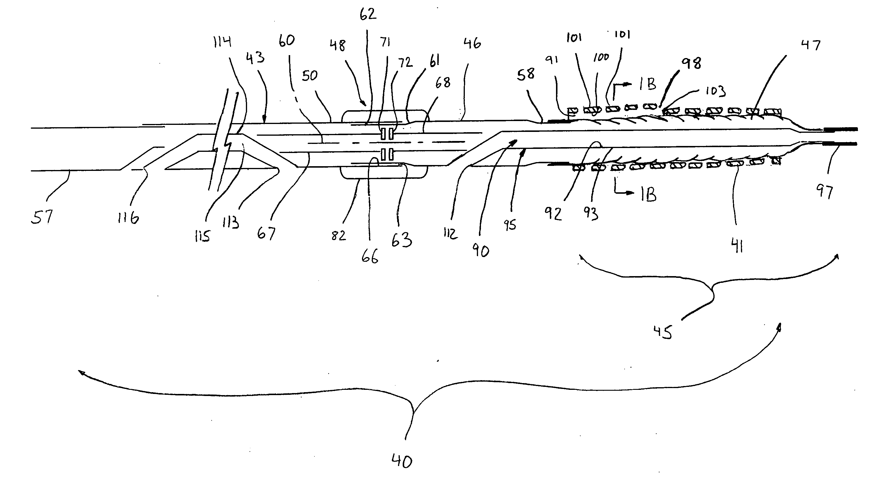
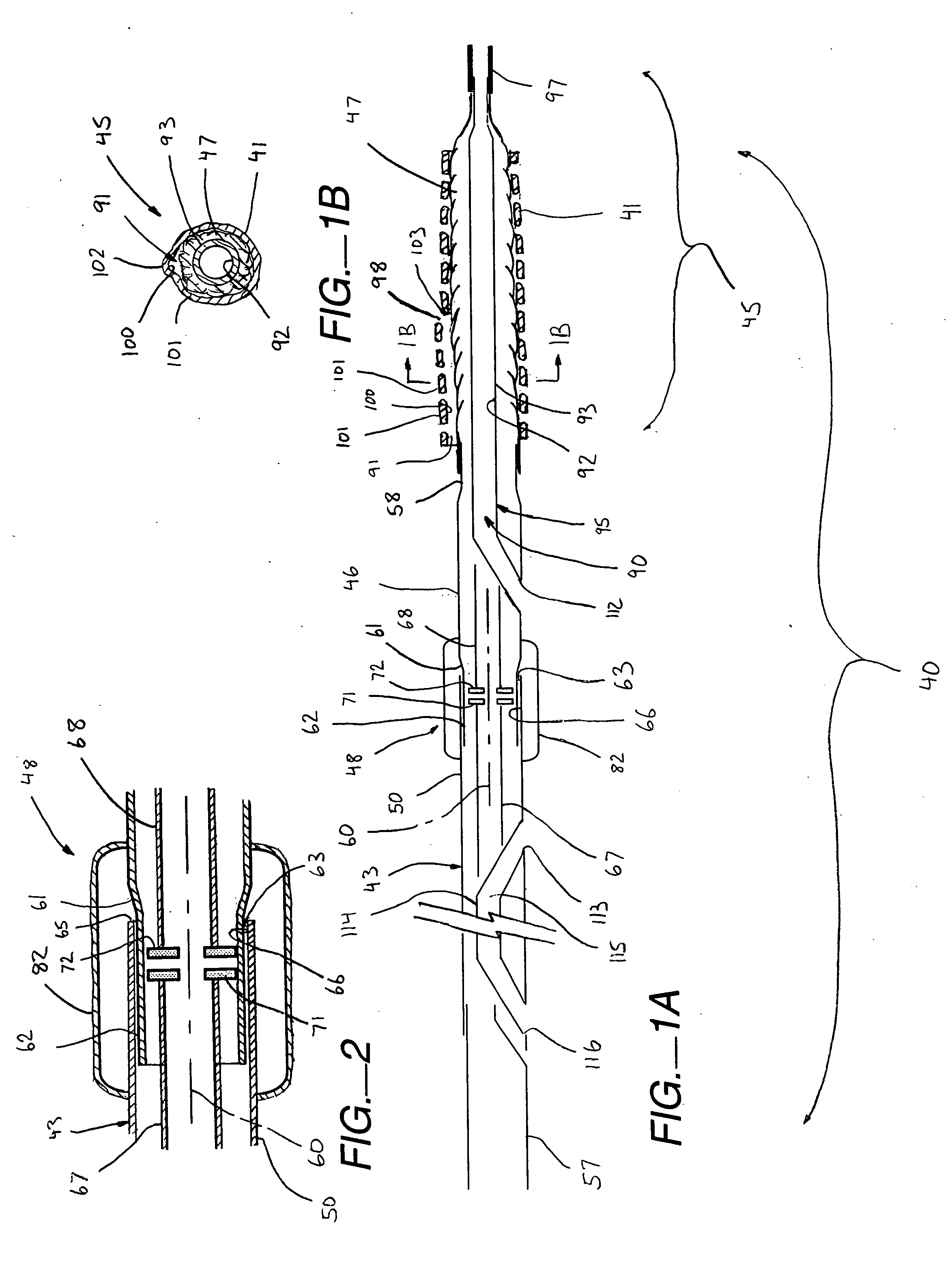
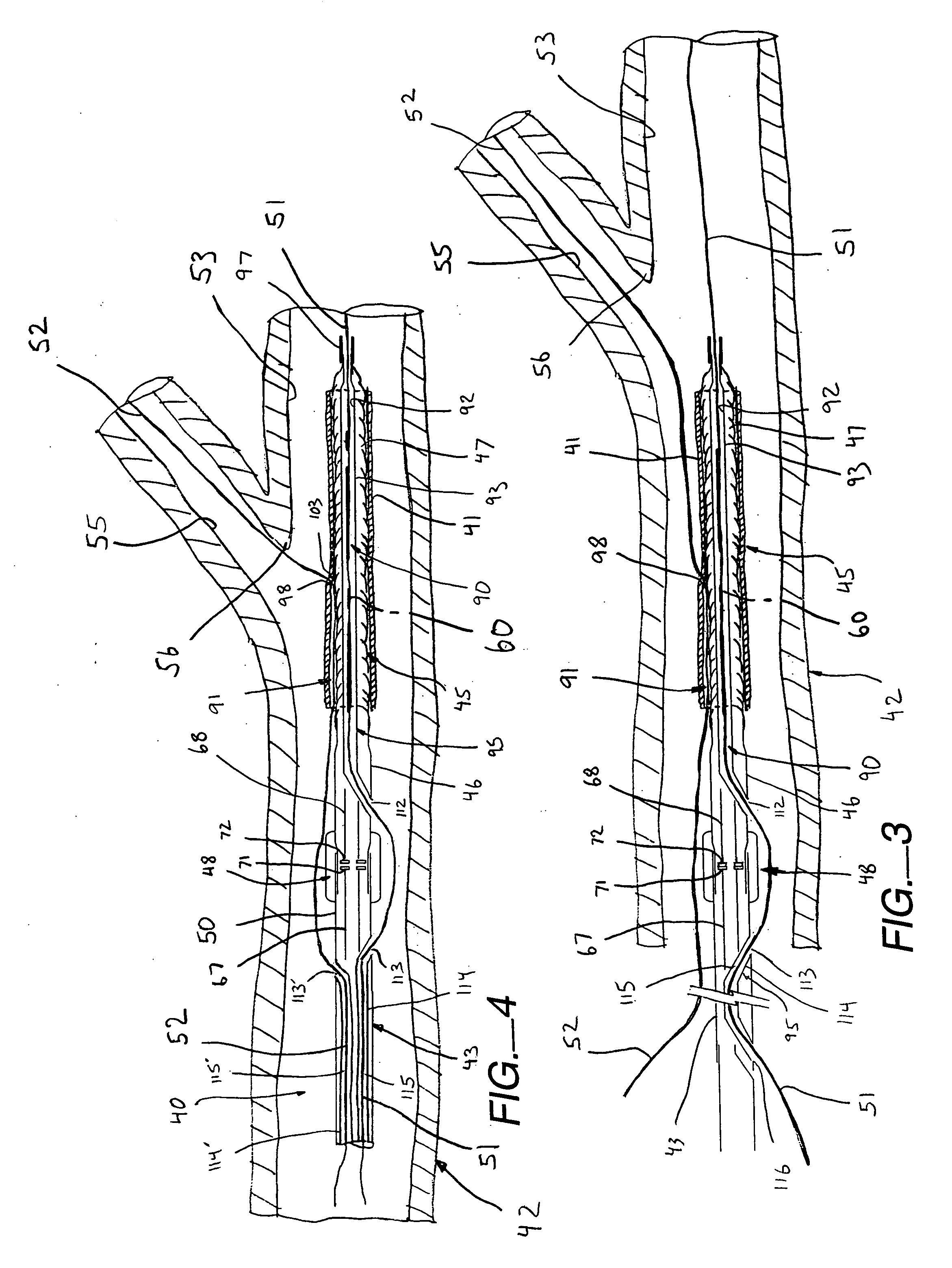
[0068] Referring now to FIGS. 1-5, a stent delivery system, generally designated 40, is described that delivers and deploys a radially expandable stent 41 (e.g., a bifurcation stent) at a strategic orientation and location in a body vessel 42. The delivery system 40 includes an elongated shaft 43 sized suitably for insertion into the body vessel 42. A stent deployment assembly 45 includes a tubular distal transition portion 46 su...


PUM


Abstract

A stent delivery system is disclosed for delivering and deploying a radially expandable stent at a strategic orientation and location in a body vessel. The delivery system includes an elongated flexible tubular shaft sized suitably for insertion into the body vessel. A stent deployment assembly includes a distal transition portion supporting a dilator device adapted for radial expansion about a longitudinal axis of the deployment assembly from a non-expanded condition to a radially expanded condition. The dilator device is configured to support the stent thereon in the non-expanded condition and in predetermined orientation relative the deployment assembly. A rotational clutch assembly rotatably mounts the transition portion to a distal portion of the tubular shaft such that the deployment assembly is substantially torsionally isolated from the tubular shaft, about a longitudinal axis of the clutch assembly. This enables the stent deployment assembly to rotate substantially independently of the tubular shaft for strategic orientation of the dilator device during advancement through the body vessel.

Description

RELATED APPLICATION DATA [0001] The present application is a continuation application of U.S. application Ser. No. 11 / 441,388, naming Von Oepen et al as inventors, filed Jun. 24, 2006 and entitled BIFURCATION STENT DELIVERY CATHETER ASSEMBLY AND METHOD; which in turn claims priority under 35 U.S.C. §119 to U.S. Provisional Application Ser. No. 60 / 684,613, naming Von Oepen et al as inventors, filed May 24, 2005 and entitled the same; and U.S. Provisional Application Ser. No. 60 / 736,637, naming Von Oepen et al as the inventors, filed Nov. 15, 2005 and entitled the same, all of which are incorporated herein by reference in their entirety and for all purposes.FIELD OF THE INVENTION [0002] The present invention relates generally to catheters and systems used for delivering devices such as, but not limited to, intravascular stents and therapeutic agents to sites within vascular or tubular channel systems of the body. More particularly, it relates to delivery catheters and systems for deli...

Claims


Application Information

Patent Timeline
Patent Type & Authority Applications(United States)
IPC IPC(8): A61F2/06
CPCA61F2/856A61F2/954A61M2025/1015A61M2025/09125A61F2/958
Inventor OEPEN, RANDOLF VONRIETH, THOMASCOFFEY, LORCANZUCKER, ARIKYRIBARREN, TRAVIS
Owner ABBOTT LAB INC
Features
  • R&D
  • Intellectual Property
  • Life Sciences
  • Materials
  • Tech Scout
  • Unparalleled Data Quality
  • Higher Quality Content
  • 60% Fewer Hallucinations
Learn More