
Pressure boost for vehicle rear brake circuits

a technology for rear brakes and pressure boosts, which is applied in the field of vehicle rear brake circuits, can solve the problems of corresponding greater vehicle deceleration, transfer of vehicle weight from the rear wheels to the front wheels, and design of brake calipers that are not sufficient to ensure the front, and achieve the effect of improving braking

Active Publication Date: 2006-12-21
KELSEY HAYES CO
View PDF44 Cites 22 Cited by
  • Summary
  • Abstract
  • Description
  • Claims
  • Application Information

AI Technical Summary

Benefits of technology

[0012] This invention relates to an algorithm for boosting the hydraulic pressure in the rear circuits of a vehicle hydraulic brake system to provide enhanced braking when the vehicle is heavily loaded and / or towing a trailer.

Problems solved by technology

On high mu surface roads, however, the greater coefficient of friction of the road surface allows a harder brake application with a corresponding greater vehicle deceleration.
The increase in vehicle deceleration results in a transfer of vehicle weight from the rear wheels to the front wheels.
With the transfer of vehicle weight, the design of the brake calipers may not be sufficient to assure that the front brakes lock up before the rear brakes.
The different rates of increase result in a greater braking effort occurring at the front wheel brakes than at the rear wheel brakes such that the front wheel brakes lock up before the rear wheel brakes.
However, under certain conditions, such as when a vehicle is towing a trailer or is heavily loaded, as with a truck, the rear longitudinal tire force may not be fully utilized.

Method used


Image

  • Pressure boost for vehicle rear brake circuits
  • Pressure boost for vehicle rear brake circuits
  • Pressure boost for vehicle rear brake circuits

Examples


Embodiment Construction

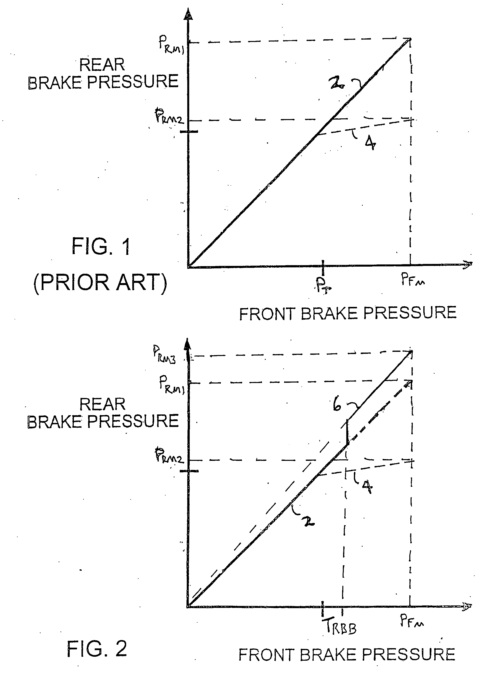
[0027] The present invention contemplates boosting the rear brake circuit pressure in a vehicle brake system under certain operational conditions. Referring again to the drawings, there is illustrated in FIG. 2, the response of a vehicle brake system in accordance with the present invention. Curves shown in FIG. 2 that are similar to curves shown in FIG. 1 have the same numerical identifiers. Also, while linear relationships between the front and rear brake circuit pressures are shown, it will be appreciated that the invention also may be practiced with a non-linear relationship between the pressures (not shown). The response, which is labeled 6, represents the relationship between front and rear brake circuit pressures when rear brake boost conditions exist. Under normal operating conditions, the brake pressures will follow the line labeled 2, if proportioning is not included in the brake system, or the pressures will follow the line labeled 4, if proportioning is included in the b...


PUM


Abstract

Under certain operating conditions, the pressure applied to a vehicle rear brake circuit is increased above the pressure applied to the vehicle front brake circuit to enhance stopping of the vehicle.

Description

CROSS-REFERENCE TO RELATED APPLICATIONS [0001] This application claims the benefit of U.S. Provisional Application No. 60 / 676,394, filed Apr. 29, 2005, the disclosure of which is incorporated herein by reference.BACKGROUND OF THE INVENTION [0002] This invention relates in general to vehicle brake systems and in particular to an algorithm for boosting the pressure in the rear circuits of such a brake system to provide enhanced braking when the vehicle is heavily loaded and / or towing a trailer. [0003] Typically, vehicles are equipped with hydraulic brake systems having a dual master cylinder which includes separate front and rear hydraulic brake fluid reservoirs and actuating chambers. The front and rear actuating chambers are connected to front and rear brake cylinders, respectively, to define separate front and rear brake circuits. Depressing a brake pedal, which is connected by a mechanical linkage to the master cylinder, applies hydraulic pressure through both brake circuits to th...

Claims


Application Information

Patent Timeline
Patent Type & Authority Applications(United States)
IPC IPC(8): G06F19/00
CPCB60T8/1708B60T2250/02B60T8/266B60T8/1766
Inventor HALLER, MARKLUBISCHER, FRANKBARTOL, MARKGINGER, GREGSPIEKER, ARNOLD H.ROMANOWSKI, MIKE
Owner KELSEY HAYES CO
Features
  • Generate Ideas
  • Intellectual Property
  • Life Sciences
  • Materials
  • Tech Scout
  • Unparalleled Data Quality
  • Higher Quality Content
  • 60% Fewer Hallucinations
Learn More