Method and apparatus for selective solar control

a solar control and selective technology, applied in the direction of lighting and heating apparatus, door/window protective devices, using daylight, etc., can solve the problems of difficult or expensive construction and service, prior approaches to controlling the level of solar radiation passing through architectural structures, and difficult or expensive construction and maintenan

Inactive Publication Date: 2006-12-28
CPI DAYLIGHTING
View PDF25 Cites 47 Cited by
  • Summary
  • Abstract
  • Description
  • Claims
  • Application Information

AI Technical Summary

Benefits of technology

[0020] The selective solar systems of the present invention thus can continuously control and reliably maintain a desired balance between light transmission and solar performance, fostering a daylighted, comforting, livable, productive and energy efficient environment in interior spaces all year round. The systems may be fully automatic, with

Problems solved by technology

The known approaches to controlling the amount of solar radiation admitted through glazing panel systems, however, are limited, are generally difficult or expensive to construct and service, and are often unable to accommodate excessive positive or negative loading.
Prior approaches to controlling the level of solar radiation passing through architectural structures have been of only limited usefulness.
Furthermore, louver blinds are difficult and expensive to assemble, apply, operate, maintain and replace, and cannot be readily adapted for use in non-vertical applications, large glazed roofing areas or in applications in which it is either desirable or necessary to control the flexible members from only one end.
For example, one of the limitations of the '255 patent is the limited range of solar radiation manipulation and deflection that it provides.
For example, a limitation that results from manipulating the solar radiation as a single undivided source is the inability to allow the infrared portion of the solar spectrum (700-2800 nm) to pass while blocking the passage of visible light and/or UV radiation, or any other spectral combinations thereof.
Another limitation is the inability to allow UV transmission when required, for example, for animal habitats, solaria, and enclosures for photodegradable waste or zoo applications.
The panels described in the '255 patent do not provide an optimal solution to these challenges.
Another limitation of '255 patent panel system is that the opaque surfaces of the radiation-blocking members cannot efficiently deflect direct solar radiatio

Method used


Image

  • Method and apparatus for selective solar control
  • Method and apparatus for selective solar control
  • Method and apparatus for selective solar control

Examples


Embodiment Construction

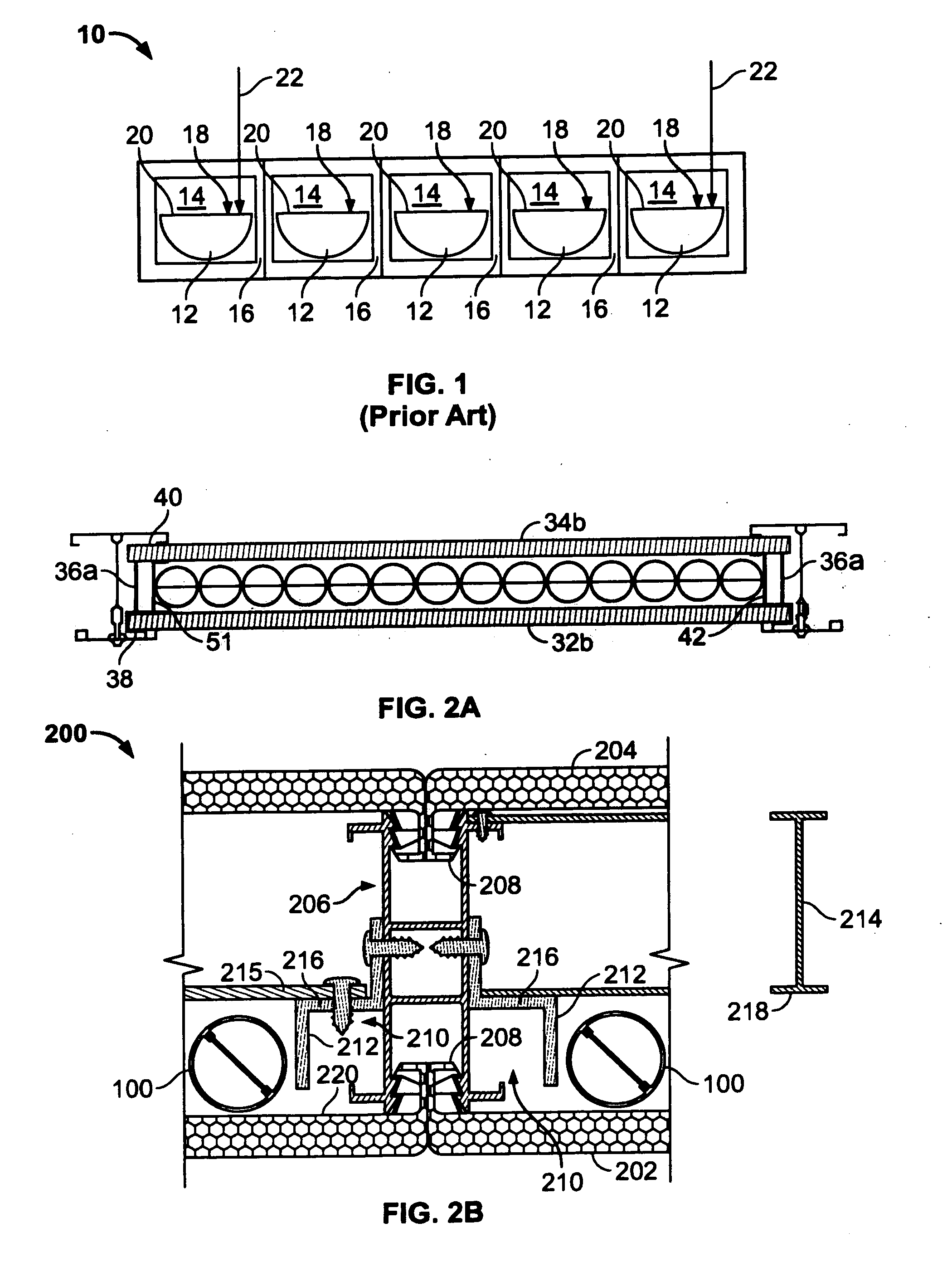
[0035] Turning first to FIG. 1, an elevational view of a transparent or translucent panel 10 in accordance with the teaching of prior U.S. Pat. No. 6,499,255 is shown. Panel 10 includes a series of half-cylinder louvers 12 rotatably mounted in a series of adjacent, segregated cells 14 separated by walls 16. Louvers 18 each have an opaque top surface 20. Thus, in the illustrated embodiment where the louvers are in the fully closed position, light rays 22 strike opaque surfaces 20, which block light transmission through the opaque louvers and the panel. The opaque top surface blocks the light / solar spectral radiation and therefore absorbs the solar radiation rather then reflecting or deflecting it. Additionally a portion of the absorbed solar radiation is emitted as heat into the interior space below the panel. The lack of selective solar reflection or deflection properties as well as the inability to selectively transmit or block the solar spectrum creates undesirable glare and ineff...


PUM

PropertyMeasurementUnit
Angleaaaaaaaaaa
Diameteraaaaaaaaaa
Transparencyaaaaaaaaaa

Abstract

This invention is a system of transparent or translucent panel units that permit selective transmission of light and solar radiation or glare across the system and can be adjusted and controlled according to a user's varying needs using light-controlling members mounted for rotation about their longitudinal axes. The system can illuminate the interior space by reflected sunlight, conducting both light from the brightest part of the sky and low-angle sunlight efficiently into the interior space, and also shading or deflecting the intense light found when the sun is at high elevation. Alternatively, the amount of a selected portion of the radiation spectrum passed through the system can be set at will, and can be amplified to allow increased light passage and transmission.

Description

CROSS REFERENCE TO RELATED APPLICATION [0001] This patent application claims the benefit of U.S. Provisional Serial Application No. 60 / 689,176, filed Jun. 10, 2005, which is hereby incorporated by reference in its entirety.FIELD OF THE INVENTION [0002] This invention relates to architectural structures designed to pass light and, more particularly, to transparent / translucent panel systems for harvesting the sun and controlling the level of light, spectral performance and solar or optical radiation admitted or deflected through sloped, vertical, and horizontal glazing, skylights, roofs, walls, and other architectural structures designed to pass light. This invention also relates to improved support systems for improving the reliability of such systems. BACKGROUND OF THE INVENTION [0003] Various types of transparent and translucent glazing systems are available for the construction of sloped, vertical, and horizontal glazing, skylights, roofs, walls, and other architectural structures...

Claims


Application Information

Patent Timeline
IPC IPC(8): E06B7/08
CPCE04C2/543F21V33/006E04D3/28E04D2003/0856E04D2003/285E04F10/08E06B9/24E06B9/264E06B2009/2417F21S11/00F21V5/002F21V7/22F21V9/04F21V9/06F21V14/06F21V14/08E04D3/08E04F10/10F21V7/24F21V7/28
Inventor KONSTANTINO, EITANKONSTANTIN, MOSHE
Owner CPI DAYLIGHTING
Why Eureka
Try Eureka