
Energy recovery system for rubber and plastic molding machines

a technology of energy recovery system and rubber and plastic molding machine, which is applied in the direction of machines/engines, mechanical equipment, other domestic objects, etc., can solve the problems of wasting money and resources by dumping any heated fluid (air, water, etc.) into the environmen

Inactive Publication Date: 2006-12-28
CORBETT BRADFORD G JR
View PDF9 Cites 14 Cited by
  • Summary
  • Abstract
  • Description
  • Claims
  • Application Information

AI Technical Summary

Problems solved by technology

Discharging any heated fluid (air, water, etc.) into the environment is a waste of money and resources.

Method used


Image

  • Energy recovery system for rubber and plastic molding machines
  • Energy recovery system for rubber and plastic molding machines
  • Energy recovery system for rubber and plastic molding machines

Examples


Embodiment Construction

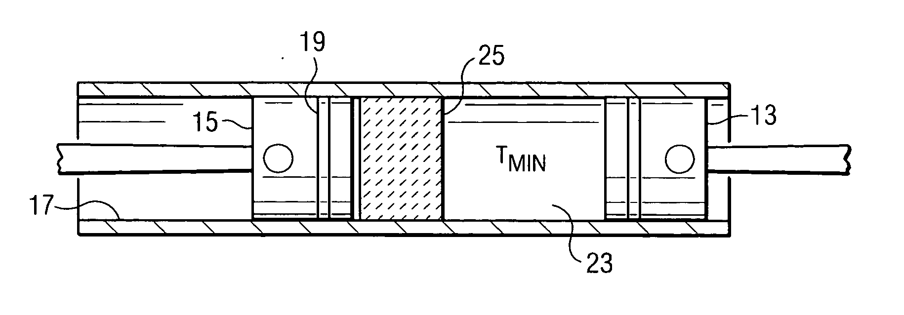
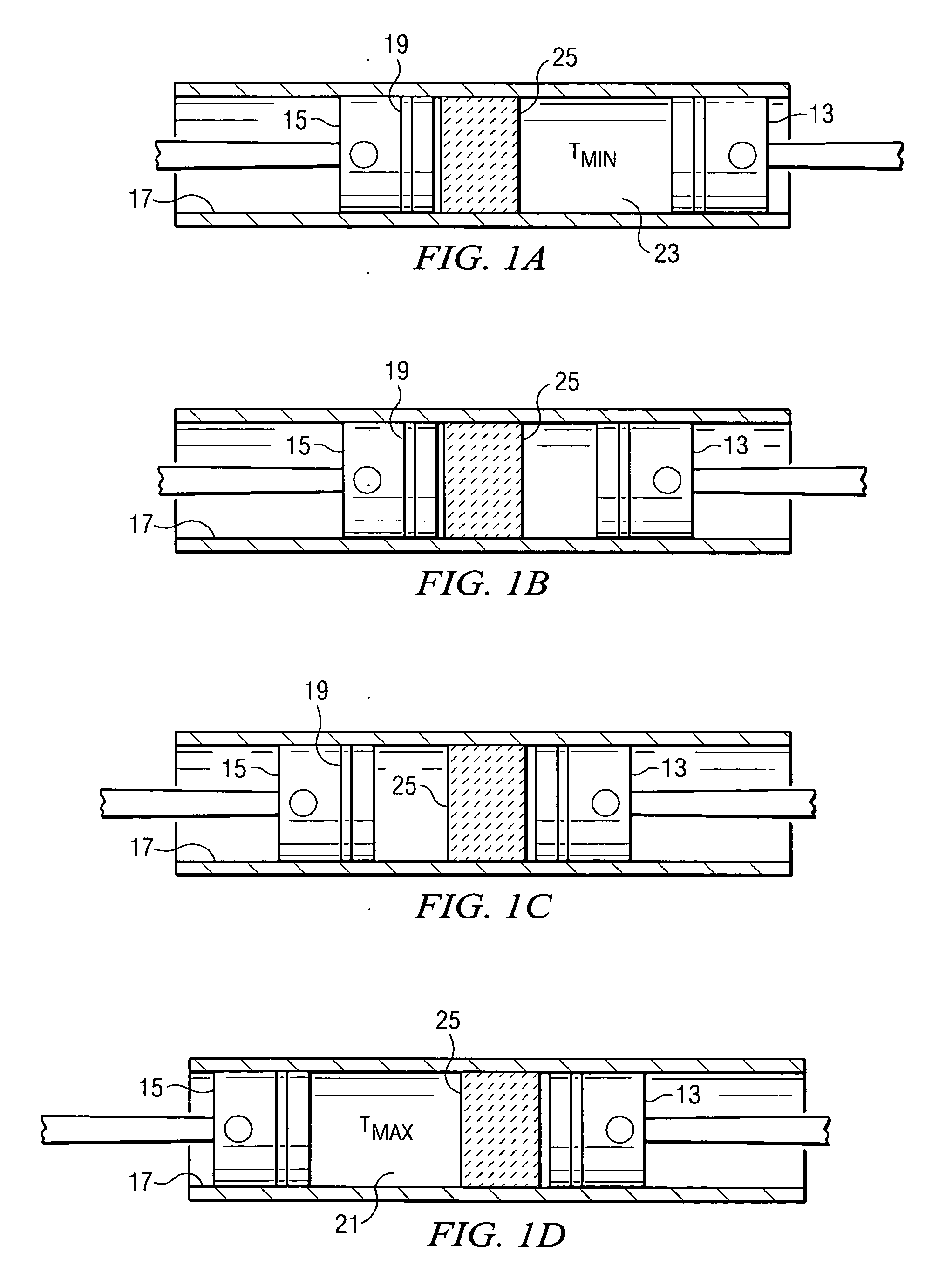
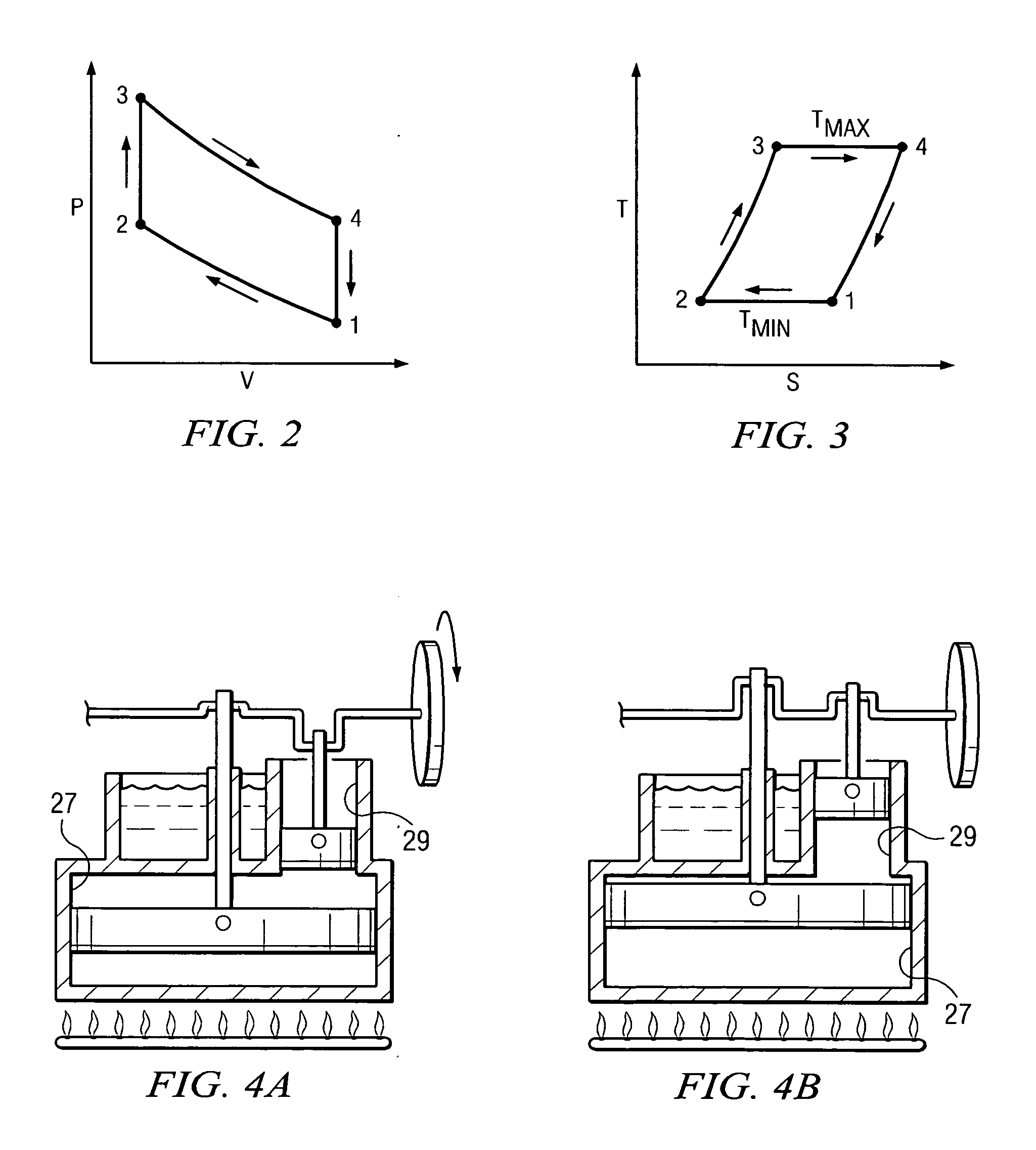
[0019] The present invention involves the use of s Stirling engine or Stirling cycle in recovering heat from an injection molding or compression molding process. Since Stirling engines can run on any heat source, they can be used to recover power from industrial waste heat sources such as those found in compression and injection molding industries. Stirling cycle machines, including engines and refrigerators, are well known in the art. Many technical articles and treatises have been written on the subject. For example, see the text by G. Walker, “Stirling Engines”, Clarendon Press, Oxford, 1980, ISBN No. 0-19-856209-8, which is considered by many to be a standard reference in the field.

[0020] Briefly stated, the principle underlying the Stirling cycle engine is the mechanical realization of the Stirling thermodynamic cycle: isovolumetric heating of a gas within a cylinder, isothermal expansion of the gas (during which work is performed by driving a piston), isovolumetric cooling, a...


PUM

PropertyMeasurementUnit
pressureaaaaaaaaaa
volumeaaaaaaaaaa
moldingaaaaaaaaaa

Abstract

An energy recovery system for a compression or injection molding operation is shown. A Stirling engine cycle is used to recover heat. The Stirling engine is driven by waste heat from the mold members or other associated parts of the injection or compression molding apparatus.

Description

CROSS REFERENCE TO RELATED APPLICATIONS [0001] The present application claims priority from the following U.S. Provisional Application Ser. No. 60 / 693,389, filed Jun. 23, 2005, entitled “Energy Recovery System for Rubber and Plastic Molding Machines,” and invented by Bradford G. Corbett, Jr.BACKGROUND OF THE INVENTION [0002] 1. Field of the Invention [0003] The present invention relates generally to injection and compression molding processes, to the equipment for forming rubber and plastic articles using compression and injection molding techniques and to a process for recovering waste energy from such processes. [0004] 2. Description of the Prior Art [0005] An almost unlimited variety of articles are produced from rubber, synthetic elastomers and plastics using compression and injection molding equipment. As one example, many kinds of equipment, ducting, piping, castings, and other parts are joined together in gasketed joints in order to form gas, liquid, electrical, chemical, or ...

Claims


Application Information

Patent Timeline
Patent Type & Authority Applications(United States)
IPC IPC(8): F02G1/04F01B29/10
CPCB29C43/027B29C43/52B29C45/72B29C47/0009F02G2254/00B29C2045/7292B29K2021/00B29L2031/7096F02G1/044B29C47/0893B29C48/03B29C48/276Y02P70/10
Inventor CORBETT, BRADFORD G. JR.
Owner CORBETT BRADFORD G JR
Learn More