Engine starter for a radio control model

a radio control model and engine technology, applied in the direction of engine starters, toys, toy aircrafts, etc., can solve the problems of broken gear series, engine may be locked, and newcomers usually have not enough experience to make a correct judgement when the engine is started

Inactive Publication Date: 2006-12-28
LIU NAI WEN
View PDF1 Cites 9 Cited by
  • Summary
  • Abstract
  • Description
  • Claims
  • Application Information

AI Technical Summary

Benefits of technology

[0008] The main objective of the present invention is to provide an improved an engine

Problems solved by technology

Consequently, engine may be locked when the fuel overly enter the carburetor due to a careless operation.
However, the newcomer usually has not enough experience to make a corr

Method used


Image

  • Engine starter for a radio control model
  • Engine starter for a radio control model
  • Engine starter for a radio control model

Examples


Embodiment Construction

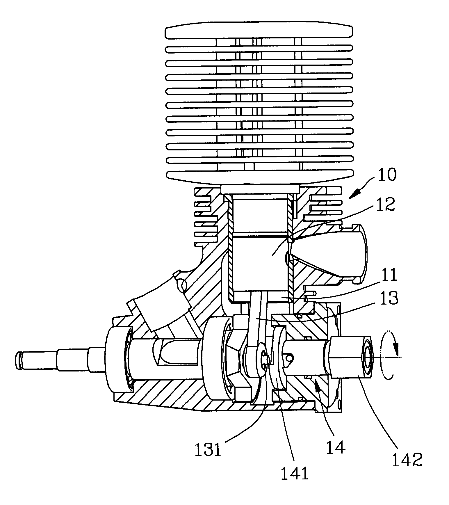
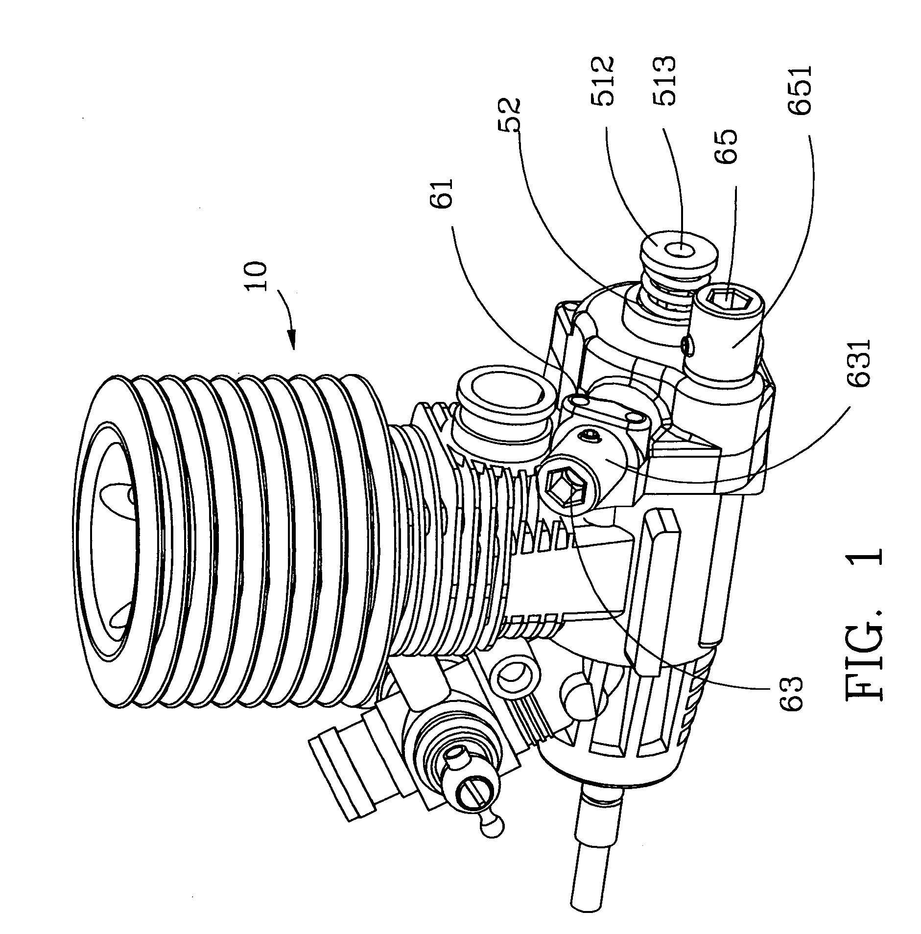
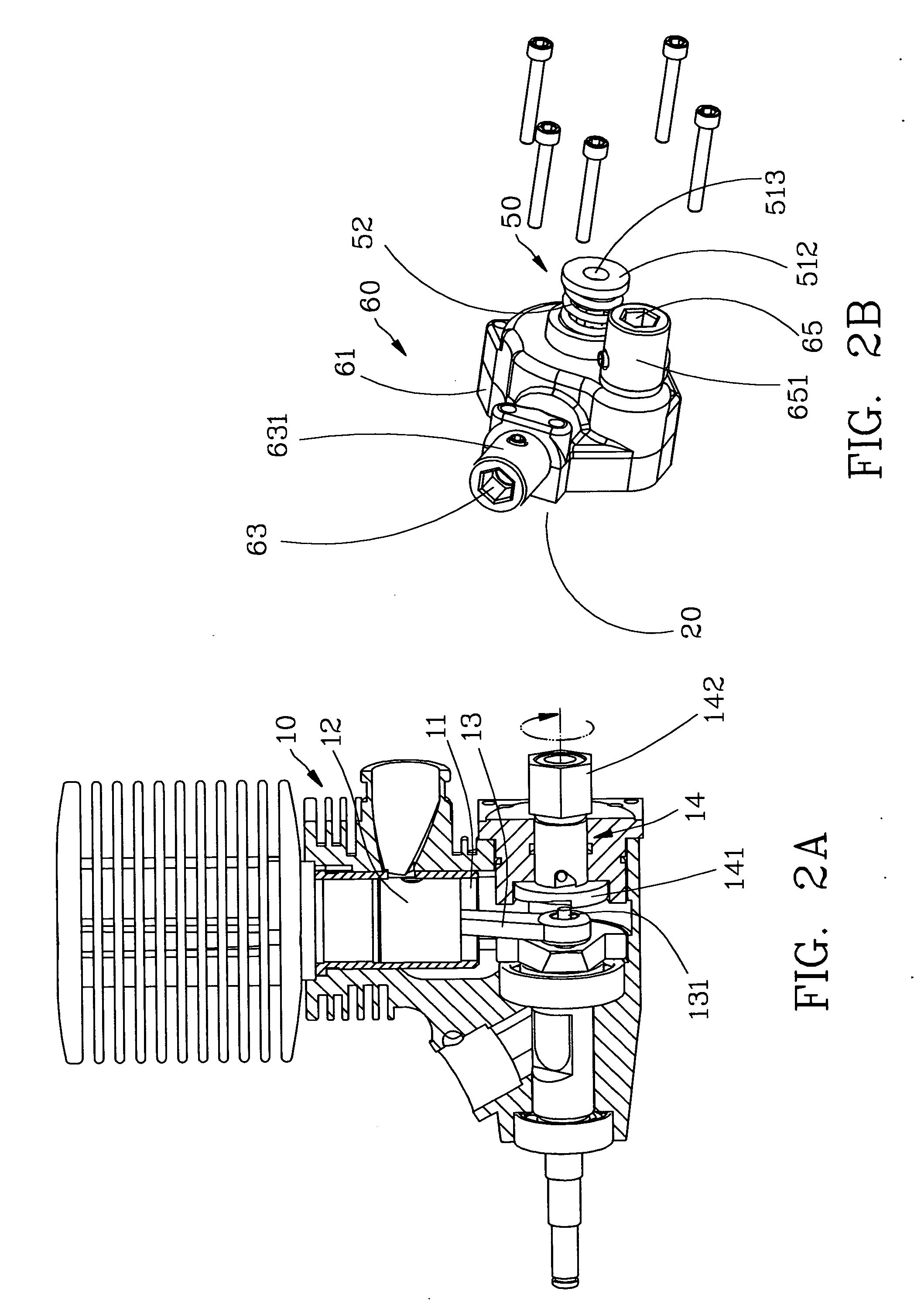
[0019] Referring to the drawings and initially to FIGS. 1-3, an engine of a radio control model comprises a body (10) including a chamber (11) defined therein. A piston (12) is movably received in the chamber (11). A crank (13) includes a first end pivotally connected to a lower portion of the piston (12) and a second end having a shaft (131) laterally extending from the crank (13). A T-shaped drive axle (14) rotatably extends through the body (10). The T-shaped drive axle (14) has a drive plate (141) radially extending from a first end thereof for driving the shaft (131) and a polygonal head (142) formed on a second end of the T-shaped drive axle (14) for connected to the engine starter of the present invention.

[0020] The engine starter in accordance with the present invention comprises an output shaft (20) concentrically connected to the second end of the T-shaped drive axle (14). The output shaft (20) has a socket (21) with a polygonal hole (not shown) for complementally receivi...


PUM


Abstract

An engine starter for a radio control model includes an output shaft concentrically connected to and synchronously rotated with a T-shaped drive axle of the engine to start the engine. A drive wheel is sleeved on the output shaft for receiving an extra power. A limit wheel is sleeved on the output and synchronously rotated with the output shaft. The limit wheel is selectively driven by the drive wheel. A gear box is secured on the engine and provided to receive the output shaft, the drive wheel and the limit wheel. A torsion adjust device is mounted to a free end of the output shaft after the output shaft extending through the gear box. The drive wheel is idle running when the torsion force from the engine is greater than that from the torsion adjust device for protecting the engine from a forced operation.

Description

BACKGROUND OF THE INVENTION [0001] 1. Field of the Invention [0002] The present invention relates to an engine starter, and more particularly to an engine starter for a radio control model. [0003] 2. Description of Related Art [0004] A conventional engine starter for a radio control model in accordance with the prior art shown in FIG. 7 comprises a body (1) with a chamber (2) defined therein and a piston (3) reciprocally movably received in the chamber (2). A lower end of the piston (3) is connected to a T-shaped drive shaft (5) via a crank (4). The T-shaped drive shaft (5) has a free end longitudinally connected to a start gear box (6). A series of gears are disposed in the start gear box (6) for driving the T-shaped drive shaft (5). An input shaft (6A) rotatably extends from the start gear box (6) for driving the series of gears via an extra power source. [0005] The fuel will be continually pumped for several seconds and slowly enter the carburetor of the engine when starting the ...

Claims


Application Information

Patent Timeline
IPC IPC(8): F02N15/06A63H17/385F02B75/34F02N15/02F02N15/10
CPCA63H27/02F02B75/34Y10T74/13F02N15/02F02N15/10F02D2400/06
Inventor LIU, NAI WEN
Owner LIU NAI WEN
Why Eureka
Try Eureka