Wet brake system for a vehicle and a utility vehicle comprising the wet brake system

a technology for wet brakes and utility vehicles, which is applied in the direction of braking systems, fluid actuated brakes, transportation and packaging, etc., and can solve the problem of unnecessary precise adjustmen

Inactive Publication Date: 2010-09-14
KAWASAKI HEAVY IND LTD
View PDF7 Cites 10 Cited by
  • Summary
  • Abstract
  • Description
  • Claims
  • Application Information

AI Technical Summary

Benefits of technology

[0008]The present invention addresses the above described conditions, and an object of the present invention is to provide a wet brake system which is capable of protecting an operating portion of an operation lever from mud and other substances from a road surface, bouncing stones, etc., and does not require precise adjustment, and a utility vehicle comprising the wet brake system.
[0011]The brake mechanism may include a ball cam mechanism that is disposed inside the case and is configured to provide engagement and disengagement between a brake friction plate coupled to the axle side and a pressing plate coupled to the case side; and the internal operation lever may be configured to operate the ball cam mechanism to provide engagement and disengagement between the friction plate and the pressing plate. With such a simple construction, a reliable braking action can be achieved by the oil pressure.
[0012]The case and other components of the wet brake system may be positioned behind an engine of the vehicle. In such a construction, the engine disposed in front protects the wet brake system from mud and other substances from the road surface, bouncing stones, etc.
[0014]The hydraulic cylinder may include an operating portion protruding into the inside of the case; and the operating portion may be coupled to the internal operation lever by a ball joint. In such a construction, an actuating force of the hydraulic cylinder can be transmitted to the internal operation lever smoothly.
[0015]The hydraulic cylinder may further include a piston portion provided to be movable in an axial direction thereof by an action of an oil pressure, the piston portion having an axial end surface which is configured to make curved-surface contact with a base end of the operating portion. In this case, the operating portion may be configured to be movable in the axial direction of the piston portion and to be movable so as to be tilted with respect to the axial direction by the action of the oil pressure via the piston portion, for actuating the internal operation lever. In such a construction, the force of the hydraulic cylinder can be transmitted to the internal operation lever smoothly, even when an actuating angle of the hydraulic cylinder changes according to the rotation of the internal operation lever.
[0016]A case of the hydraulic cylinder may have an air release opening oriented upward to release air in a cylinder portion accommodating the piston. In such a construction, air release from the case of the hydraulic cylinder can be easily accomplished during assembly, and maintenance therefore becomes easy.

Problems solved by technology

In addition, precise adjustment becomes unnecessary.

Method used


Image

  • Wet brake system for a vehicle and a utility vehicle comprising the wet brake system
  • Wet brake system for a vehicle and a utility vehicle comprising the wet brake system
  • Wet brake system for a vehicle and a utility vehicle comprising the wet brake system

Examples


Embodiment Construction

[0029]Now, a utility vehicle according to an embodiment of the present invention will be described with reference to the accompanying drawings. In this embodiment described below, directions are referenced from the perspective of a rider (not shown) riding in a utility vehicle of FIG. 1, except as otherwise specified.

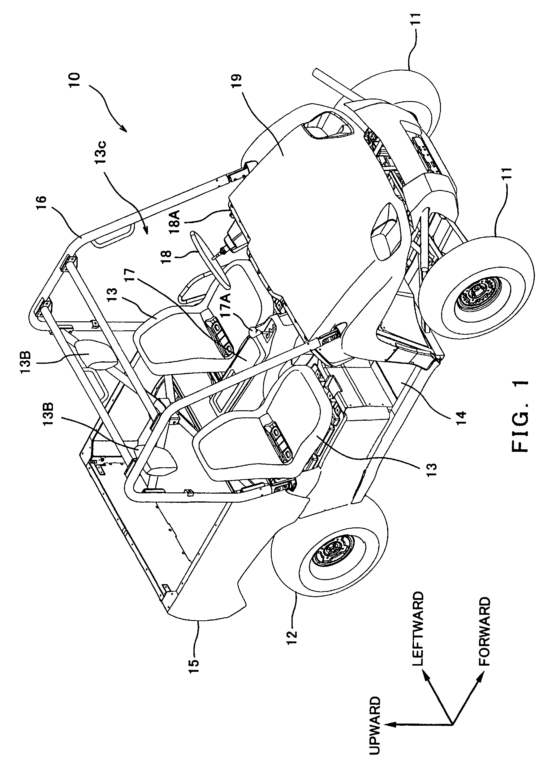
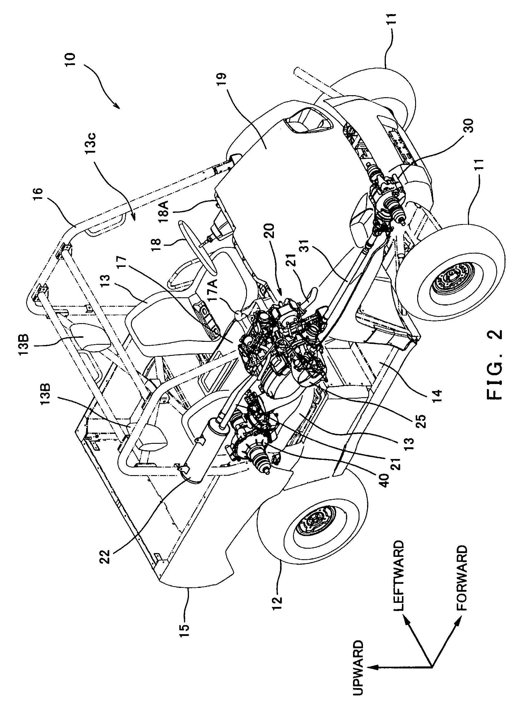
[0030]FIG. 1 is a perspective view of the utility vehicle equipped with a wet brake system according to an embodiment of the present invention, as viewed from rightward and forward. As shown in FIG. 1, the utility vehicle 10 may be, for example, a golf cart or a hunting truck for sport activities, a farming truck for working purpose, etc. The utility vehicle 10 may be a vehicle equipped with three wheels or five or more wheels, instead of four wheels as illustrated in this embodiment.

[0031]The utility vehicle 10 includes a passenger riding cabin 13c formed between front wheels 11 and rear wheels 12. Two seats 13 are arranged in the cabin 13c in a lateral direction of a ...


PUM


Abstract

A wet brake system for a vehicle including a case; an internal operation lever disposed inside the case; a hydraulic cylinder which is integrally mounted to the case and is configured to actuate the internal operation lever; and a brake mechanism configured to be operated by the actuation of the internal operation lever by the hydraulic cylinder to apply a braking force to an axle of the vehicle.

Description

TECHNICAL FILED[0001]The present invention relates to a wet brake system for a vehicle and, more particularly to a wet brake system for a utility vehicle.BACKGROUND OF THE INVENTION[0002]Utility vehicles for various purposes such as leisure activities or work, for example, hunting trucks or farming trucks, commonly travel off-road. In utility vehicles equipped with dry brake systems, brake components such as a brake pad and a brake shoe tend to wear out due to adhesion of mud, dust, and other substances, decreasing the life of the brake. In contrast, in utility vehicles equipped with wet brake systems, a brake is accommodated in a case, and is less susceptible to mud, dust, and other substances, increasing its life.[0003]However, the brake systems mounted in the utility vehicles are typically configured so that a brake unit for front wheels and a brake unit for rear wheels operate in association with each other by using, for example, a cable or an oil pressure.[0004]The brake system...

Claims


Application Information

Patent Timeline
Patent Type & Authority Patents(United States)
IPC IPC(8): F16D55/04F16D65/28
CPCB60T1/062F16D55/02F16D2121/16F16D2125/38
Inventor FUJIMOTO, HIROYUKIKITAI, HARUOTAKAGI, IZUMI
Owner KAWASAKI HEAVY IND LTD
Why Eureka
Try Eureka