Magnetic driving device

a driving device and magnetic technology, applied in the direction of chucks, mechanical equipment, manufacturing tools, etc., can solve the problems of increasing complicating the working process, and complicated working process, so as to reduce the cost of fabrication, increase the productivity, and reduce the pressure applied

Active Publication Date: 2013-07-09
MENG RUI CO LTD
View PDF5 Cites 14 Cited by
  • Summary
  • Abstract
  • Description
  • Claims
  • Application Information

AI Technical Summary

Benefits of technology

[0010]According to the primary objective of the present invention, the elastic member provides a buffering effect to the magnetic member to reduce the pressure applied on the magnetic member so as to protect the magnetic member during operation of the driving shank.
[0011]According to another objective of the present invention, the driving shank is formed with a receiving chamber, and the stop ring is formed with a toothed portion engaging the peripheral wall of the receiving chamber of the driving shank so that the driving shank and the stop ring are worked easily and quickly to increase the productivity and to decrease the cost of fabrication.
[0012]According to a further objective of the present invention, the receiving chamber of the driving shank has a constant diameter without breaking the whole strength of the driving shank so that the driving shank has a greater structural strength.

Problems solved by technology

However, it is difficult to form the stop shoulder 54 in the socket 51, thereby complicating the working process, and thereby increasing the cost of fabrication.
However, it is difficult to form the retaining groove 65 in the receiving chamber 62 of the driving shank 60, thereby complicating the working process, and thereby increasing the cost of fabrication.

Method used


Image

  • Magnetic driving device
  • Magnetic driving device
  • Magnetic driving device

Examples


Embodiment Construction

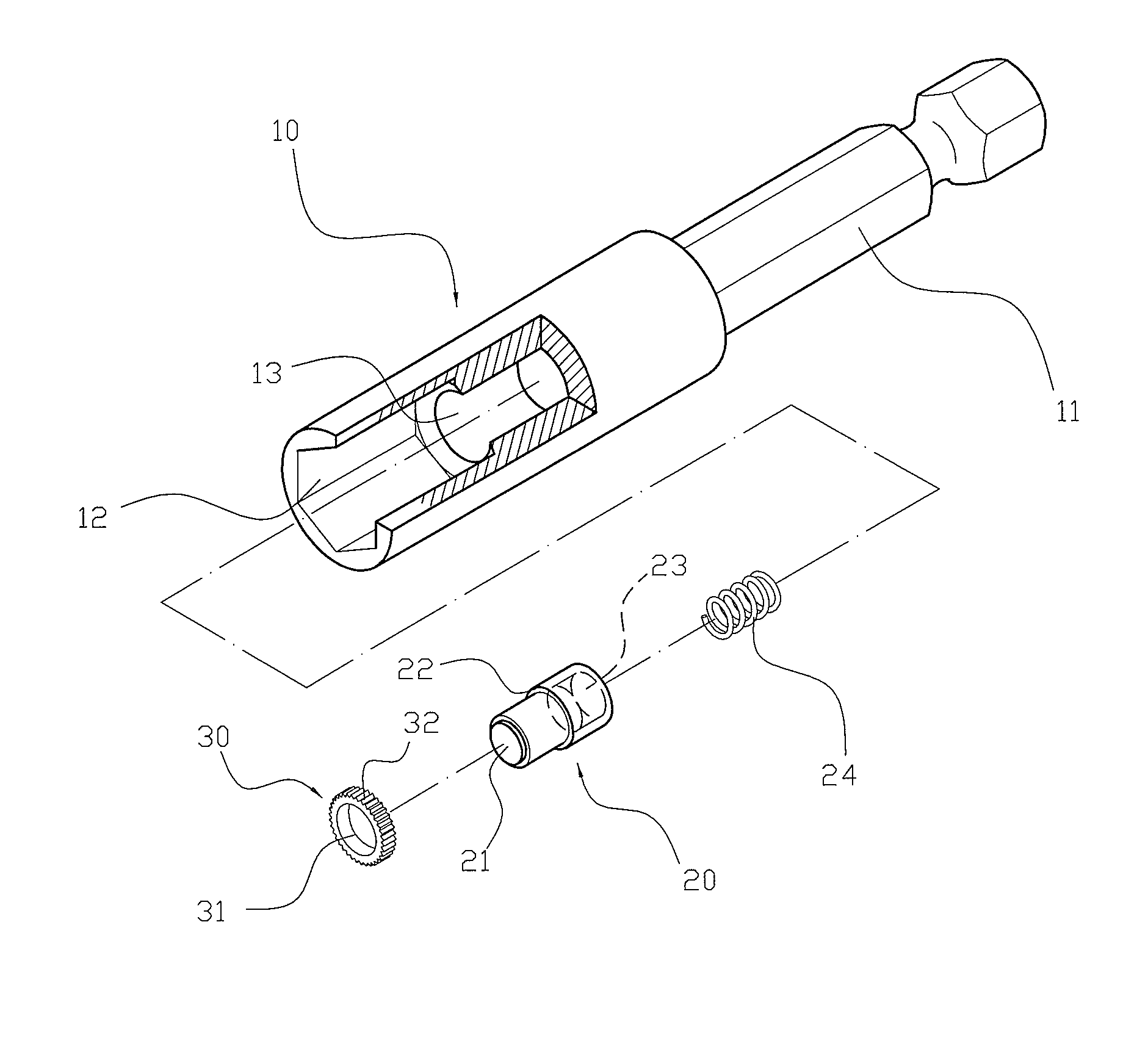
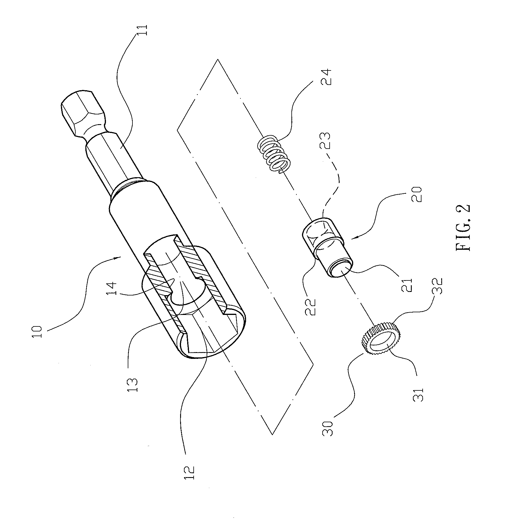
[0025]Referring to the drawings and initially to FIGS. 1-3, a driving device in accordance with the preferred embodiment of the present invention comprises a driving shank 10, a magnetic member 20 movably mounted in the driving shank 10, a stop ring 30 secured in the driving shank 10 to stop the magnetic member 20, and an elastic member 24 mounted in the driving shank 10 and biased between the driving shank 10 and the magnetic member 20 to push the magnetic member 20 toward the stop ring 30.

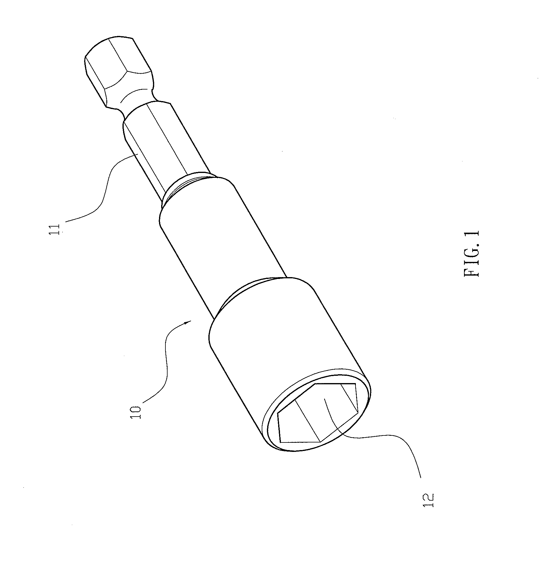
[0026]The driving shank 10 has a first end provided with a non-circular mounting post 11 and a second end formed with a non-circular mounting hole 12 and a receiving chamber 13 connected to the mounting hole 12. The receiving chamber 13 of the driving shank 10 has a circular shape and has a size smaller than that of the mounting hole 12 of the driving shank 10. The receiving chamber 13 of the driving shank 10 is located between the mounting hole 12 and the mounting post 11 of the driving shank 10...


PUM


Abstract

A driving device includes a driving shank, a magnetic member mounted in the driving shank, a stop ring secured in the driving shank to stop the magnetic member, and an elastic member biased between the driving shank and the magnetic member. The driving shank has a first end provided with a mounting post and a second end formed with a mounting hole and a receiving chamber. The stop ring has an inner wall formed with a through hole and an outer wall provided with a toothed portion engaging a peripheral wall of the receiving chamber. The magnetic member has a peripheral wall formed with a stop flange that is movable to abut the stop ring. Thus, the elastic member provides a buffering effect to the magnetic member to reduce the pressure applied on the magnetic member.

Description

BACKGROUND OF THE INVENTION[0001]1. Field of the Invention[0002]The present invention relates to a screw driving device and, more particularly, to a magnetic screw driving device that co-operates with a driving tool, such as a motorized tool, pneumatic tool or hand tool, for driving screws, screwdriver tips, drill bits or the like.[0003]2. Description of the Related Art[0004]A conventional driving device in accordance with the prior art shown in FIG. 8 comprises a driving shank 40 having a first end provided with a non-circular mounting post 43 and a second end formed with a non-circular mounting hole 41, and a magnetic member 42 secured in a bottom wall of the mounting hole 41 and extended into the mounting hole 41. When in use, the mounting post of the driving shank 40 is mounted on a driving tool, such as a motorized tool, pneumatic tool or hand tool, and the mounting hole 41 of the driving shank 40 is mounted on a driving member, such as a screwdriver tip, a drill bit and the li...

Claims


Application Information

Patent Timeline
Patent Type & Authority Patents(United States)
IPC IPC(8): B25B13/00B23B31/12B23B31/16B23B31/07B25G3/02B23B31/28B23B31/06B25G1/00B25B23/00B25B23/10B25B23/08B25B13/02B25B23/16
CPCB25B13/06B25B15/001B25B23/12Y10T279/17752Y10T279/3481Y10T279/17743Y10T279/17811Y10T279/23
Inventor TSAI, CHING-HUI
Owner MENG RUI CO LTD
Why Eureka
Try Eureka